Cylindrical mirror and coded disc glass bonding device and method based on non-coplanar marking lines

A technology of cylindrical mirror and marking line, which is applied in the field of photodetectors, can solve the problems of high uncertainty in human visual alignment, high parallelism requirements, uniformity error of slit width, etc., to solve the problem of uneven glue thickness Uniformity, improve alignment accuracy, and avoid out-of-tolerance effect

Active Publication Date: 2020-12-04
BEIJING INST OF CONTROL ENG
View PDF5 Cites 1 Cited by
  • Summary
  • Abstract
  • Description
  • Claims
  • Application Information

AI Technical Summary

Problems solved by technology

The disadvantages of this method are: 1) The uncertainty of human visual alignment is relatively high, which is 60-120 arc seconds
2) The alignment of the pressure line requires high parallelism between the three marking lines. The 0-0' marking line of the code disc and the optical slit of the cylindrical mirror are made by a wet etching process, and the uniformity error of the slit width will be large. Affects the parallelism of alignment marks and affects alignment accuracy
3) The efficiency of this method is low, and often requires multiple adjustments to align the microscope reticle, code wheel 0-bit line, and cylindrical mirror marking line
This method is only suitable for the alignment between two points, not suitable for the alignment between two lines that needs to be solved in the present invention

Method used


Image

  • Cylindrical mirror and coded disc glass bonding device and method based on non-coplanar marking lines
  • Cylindrical mirror and coded disc glass bonding device and method based on non-coplanar marking lines
  • Cylindrical mirror and coded disc glass bonding device and method based on non-coplanar marking lines

Examples


Embodiment Construction

[0042] The present invention will be further elaborated below in conjunction with embodiment.

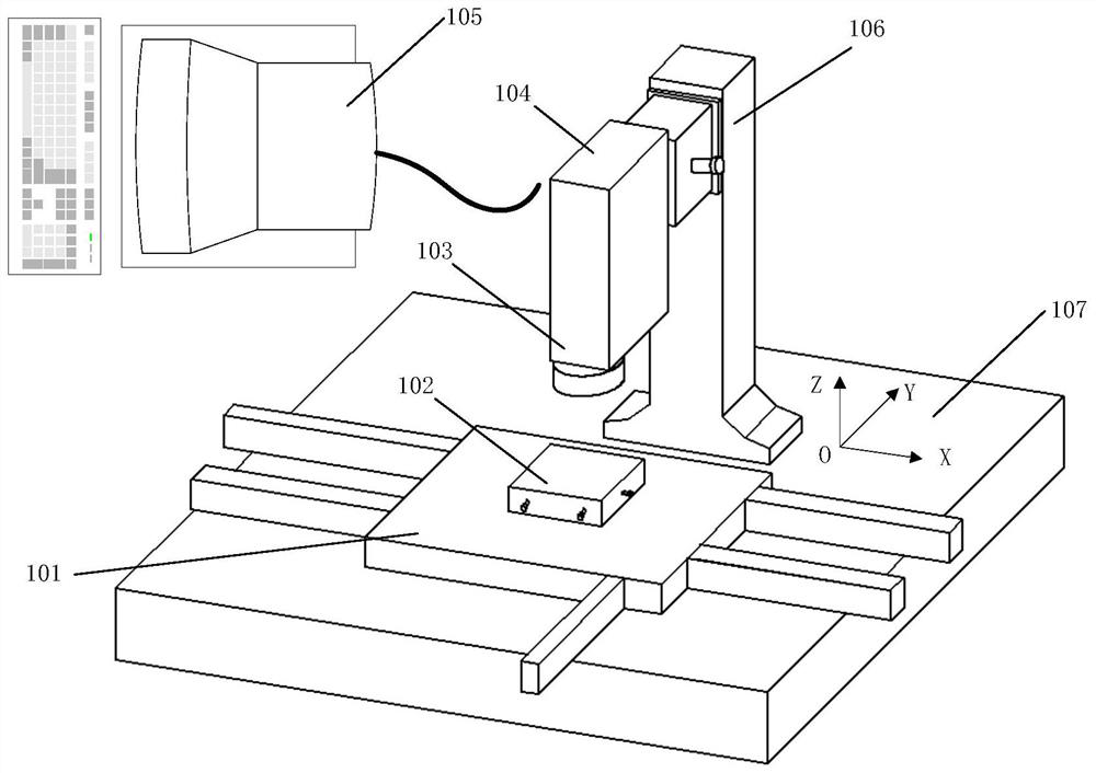
[0043] Such as figure 1 As shown, the present invention provides a cylindrical mirror and code wheel glass alignment and bonding device based on non-coplanar marking lines, the non-coplanar marking lines are respectively the optical slit of the cylindrical mirror and the code wheel 0-0 'marking line, the device includes a two-dimensional mobile platform 101, a code disc cylindrical lens bonding mold 102, a microscopic optical system 103, a CCD camera 104, a computer 105, a column 106, and a base 107;

[0044] Take the upper surface of the base 107 as the XOY plane of the measurement system coordinate system, and the coordinate axis perpendicular to the XOY plane is the Z axis of the measurement coordinate system. Move in the Y direction; the code disc cylindrical mirror bonding mold 102 is located on the two-dimensional mobile platform 101 for stacking the code disc and the cylindr...


PUM


Abstract

The invention relates to a cylindrical mirror and coded disc glass bonding device and method based on non-coplanar marking lines, and belongs to the technical field of photoelectric detectors. According to the cylindrical mirror and coded disc glass bonding device, the upper surface of a base serves as an XOY plane of a measurement system coordinate system, a coordinate axis perpendicular to the XOY plane serves as a Z axis of the measurement system coordinate system, and a two-dimensional moving platform is located on the upper surface of the base and can move in the X-axis direction and theY-axis direction of the measurement system coordinate system; a code disc cylindrical mirror bonding die is located on the two-dimensional moving platform and used for stacking a code disc and a cylindrical mirror, and the position of the code disc or the cylindrical mirror relative to the two-dimensional moving platform can be adjusted in the X-axis direction and the Y-axis direction of a coordinate system of the measuring system; the stand column is vertically installed on the base, a microscope optical system and a CCD camera are installed on the stand column, the microscope optical systemis used for imaging the stacked coded disc and cylindrical mirror, and a lens of the CCD camera is aligned with an ocular lens of the microscope optical system and used for carrying out photoelectricconversion on an image formed by the microscope optical system and uploading the image to a computer.

Description

technical field [0001] The invention relates to a bonding device and method for a cylindrical mirror and a code disk glass based on non-coplanar marking lines, and belongs to the technical field of photodetectors. Background technique [0002] The optical measurement part of the coded sun sensor is an integrated photoelectric assembly, which is made of a cylindrical mirror, a code disc, and an integrated photocell. Among them, the alignment accuracy of the two optical parts of the cylindrical mirror and the code disc directly determines the accuracy of the product. According to the task requirements, the alignment accuracy of the 0-0' marking line of the code wheel and the optical slit of the cylindrical mirror should be better than 3 μm. However, the process of bonding and aligning the code disc cylindrical mirror is difficult to operate, and the first pass rate of the process is not high, which has become a bottleneck problem restricting the production efficiency and bene...

Claims


Application Information

Patent Timeline
Patent Type & Authority Applications(China)
IPC IPC(8): G02B7/00
CPCG02B7/004
Inventor 王婧烨吕志强赵晓雨刘旭力汪艳戈强杨宇孟宪刚杨立洲高修涛邵逸恺田广武宏宇赵娜石建民范汉超
Owner BEIJING INST OF CONTROL ENG
Why Eureka
Try Eureka