Automatic identification method for epidermal layer in skin optical coherence tomography image

An optical coherence tomography and automatic identification technology, which is applied in the automatic extraction of information in skin optical coherence tomography images and the automatic identification of epidermis in skin optical coherence tomography images, can solve the problem of long time and inability to identify papillae The problem of shape structure and the subjective influence of the measurer is greatly improved, so as to achieve the effect of improving the recognition speed.

Active Publication Date: 2020-12-04
SHANGHAI INST OF OPTICS & FINE MECHANICS CHINESE ACAD OF SCI
View PDF3 Cites 0 Cited by
  • Summary
  • Abstract
  • Description
  • Claims
  • Application Information

AI Technical Summary

Problems solved by technology

[0009] All of the above methods can identify the epidermis, but the manual method takes a long time and is greatly influenced by the subjectivity of the measurer; the method of prior art 2 can only obtain the average thickness of the epidermis, which can be judged according to the peak value of the gray scale of the image column The dividing line method has only one epidermis-dermis dividing point in each column by default, and the curved papillae structure on the epidermis-dermis dividing line cannot be recognized; the method in the prior art 3 considers the image intensity from the low reflection to the higher reflection band The excessive changes of the epidermis-dermis boundary, but for psoriasis and other diseases caused by the decrease in the strength of the dermis, such as the image in the prior art 1, the judgment results of this method are quite different from the results of the epidermis obtained by histology

Method used


Image

  • Automatic identification method for epidermal layer in skin optical coherence tomography image
  • Automatic identification method for epidermal layer in skin optical coherence tomography image
  • Automatic identification method for epidermal layer in skin optical coherence tomography image

Examples


Embodiment Construction

[0037] The present invention will be further described below with reference to the embodiments and the accompanying drawings, but will not limit the scope of the invention.

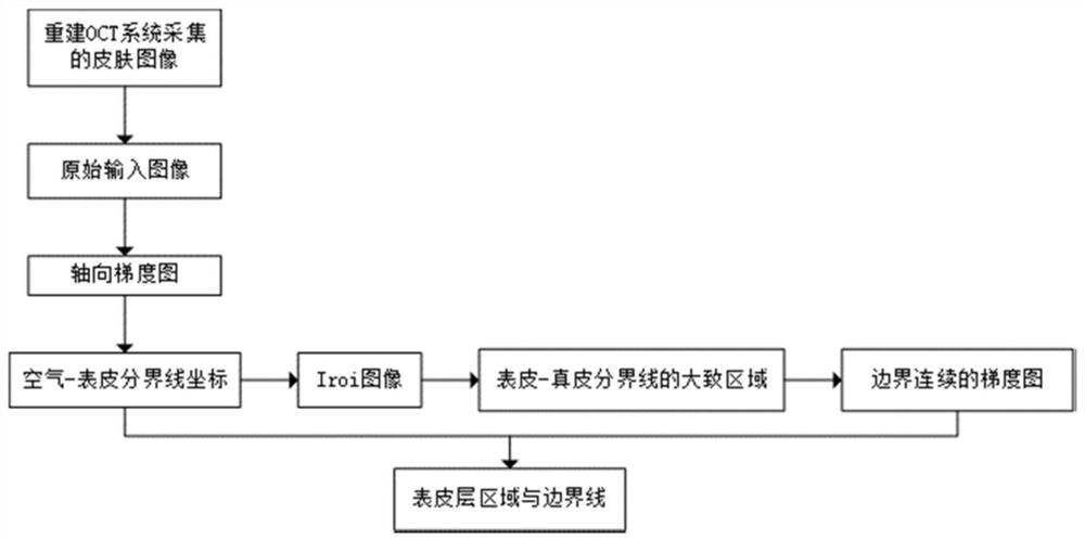
[0038] See figure 1 It is a flow chart of the automatic identification method of the skin optical coherence tomography image of the present invention. Includes the following steps:

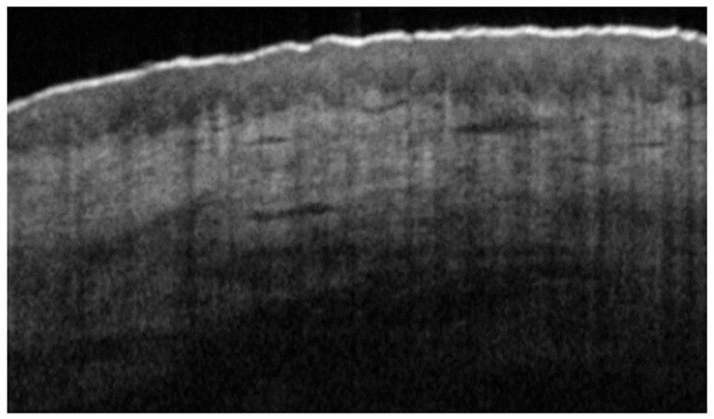
[0039] 1 Using the optical coherent chromatographic imaging system, the skin of the eczema is not related to the plaque portion, and after the logarithmic transformation is processed, a two-dimensional original input image is obtained, which is recorded as an image I, such as figure 2 Indicated. Defining the first pixel of the first line of the image as the origin, the horizontally to the right of the horizontal scanning distance, the vertical downward ordinate z is a longitudinal imaging depth, the two-dimensional image has a total of 752 columns.

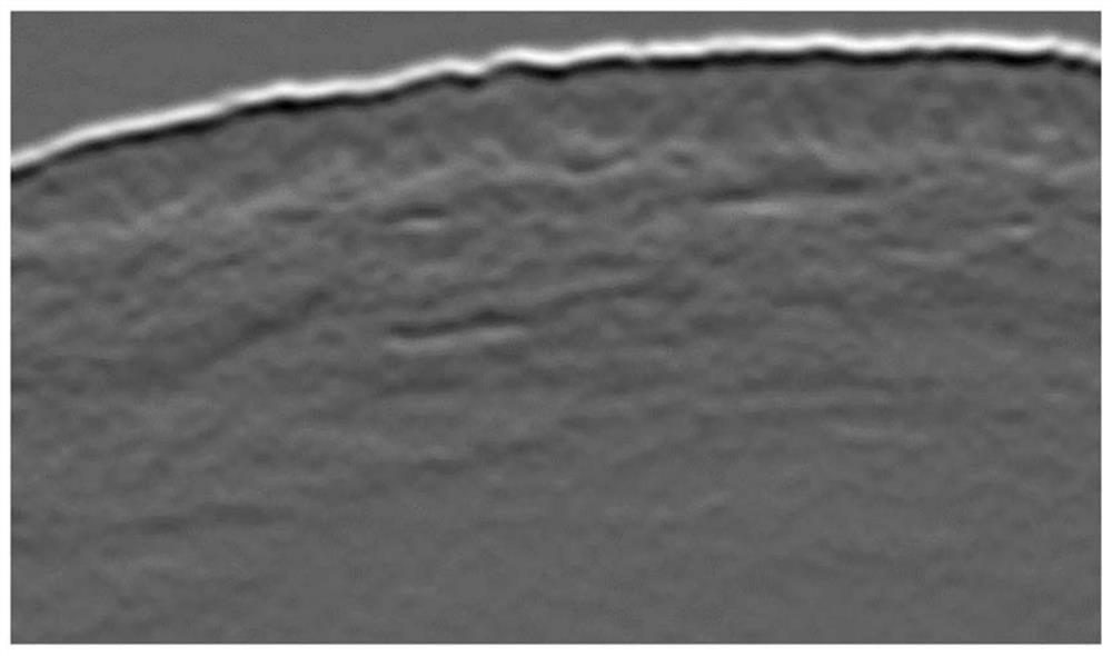
[0040] 2 A axial direction for the original input image I, the Sigma of the Gaus...


PUM


Abstract

The invention discloses an automatic identification method for an epidermal layer in a skin optical coherence tomography (OCT) image. The method comprises the following steps: obtaining an air epidermis boundary by searching the position of an axial gradient maximum value of each column in a skin OCT two-dimensional image and combining boundary continuity; taking out a certain number of pixels ofeach boundary pixel in the image in the depth direction to form a new image, performing sliding window processing on the new image to obtain an average signal of each column, and obtaining an approximate area of an epidermal-dermal boundary according to a peak value; obtaining a continuous gradient boundary line through multi-scale topology transfer; in the image, employing seed filling and a morphological algorithm to identify an area where an epidermal layer is located, and extracting a boundary position of the epidermal layer area through a boundary tracking algorithm. The method does not need manual recognition, can automatically segment the curved mastoid structure at the epidermis boundary, and is suitable for a skin OCT image with weakened corium layer signal intensity caused by dermatitis and other diseases.

Description

Technical field [0001] The present invention relates to optical coherence tomography (Optical Coherence Tomography, referred to as the OCT), in particular a method for automatic extraction of the skin image information optical coherence tomography, and more particularly a skin optical coherence tomography image table automatic recognition cortex. Background technique [0002] Optical coherence tomography (Optical Coherence Tomography, hereinafter referred to as OCT) is a backscattered light based on the detected low-coherence light interferometry sample biomedical imaging technology, non-invasive, high-resolution, detection of biological tissues inside the body of the micro- structure. The early 1990s, MIT J.G.Fujimoto and D.Huang, who first proposed the concept, structure and access to the images of the retina and coronary such as in vitro tissue. In recent years, gradually expanding its application areas, including dermatology, cardiovascular, dental and neurology and so on. ...

Claims


Application Information

Patent Timeline
IPC IPC(8): G06T7/13G06T7/12G06T7/187G06T7/155G06T7/00
CPCG06T7/13G06T7/12G06T7/187G06T7/155G06T7/0012G06T2207/10101G06T2207/30088
Inventor 杨晨铭李中梁南楠张茜欧阳君怡刘腾步扬王向朝
Owner SHANGHAI INST OF OPTICS & FINE MECHANICS CHINESE ACAD OF SCI
Why Eureka
Try Eureka