
Laser emission module and laser radar with same

A laser emission module and laser technology, applied in the field of optics, can solve the problems of longer calibration time, larger size of the emission module, and rise in manufacturing costs, etc., to achieve heat dissipation and reliability, prevent offset, and reduce length Effect

Active Publication Date: 2020-12-04
锐驰智光(北京)科技有限公司
View PDF5 Cites 0 Cited by
  • Summary
  • Abstract
  • Description
  • Claims
  • Application Information

AI Technical Summary

Problems solved by technology

[0005] However, in the above-mentioned structure, multi-line lidar is realized by stacking multiple substrates, so when the number of lines of lidar reaches 64 or even 128 lines, the size of the transmitting module will become larger, and because it is necessary to set a side for each The laser-emitting substrates are ray-corrected separately, so it takes a long time to calibrate all the substrates, which slows down the production speed of LiDAR and increases the manufacturing cost

Method used


Image

  • Laser emission module and laser radar with same
  • Laser emission module and laser radar with same
  • Laser emission module and laser radar with same

Examples


Embodiment Construction

[0036] The technical solutions of the embodiments of the present invention will be described in detail below with reference to the drawings of the embodiments of the present invention. Apparently, the embodiments disclosed below are only some of the embodiments of the present invention, not all of them. Based on the following embodiments, all other embodiments obtained by persons of ordinary skill in the art without making creative efforts belong to the protection scope of the present invention.

[0037] And, in the description of the present invention, the orientation or positional relationship indicated by the terms "upper", "lower", "left", "right", "front", "rear" etc. is based on the orientation or positional relationship of the drawings, And it is only a simplified description for the convenience of describing the present invention, but does not indicate or imply that the device or element referred to must have a specific orientation, be constructed and operated in a spe...


PUM


Abstract

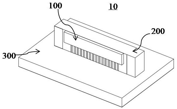
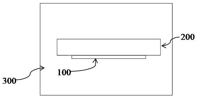
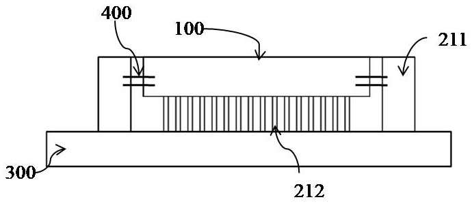
The invention discloses a laser emission module and a laser radar with the same. A laser emission module according to an embodiment of the invention comprises a substrate, a support portion arranged on the substrate and having a metal pattern formed on a surface thereof, and a light-emitting part arranged on the support portion and comprising a plurality of lasers capable of emitting laser light,and electrically connected to the substrate through the metal pattern.

Description

technical field [0001] The invention relates to the field of optics, in particular to a laser radar and a transmitting module of the laser radar. Background technique [0002] In the field of autonomous driving, autonomous vehicles can detect surrounding objects with the help of devices such as Lidar (LIDAR). The laser radar can emit a laser beam to the surrounding three-dimensional space as a detection signal, and make the laser beam irradiate the objects in the surrounding space and then be reflected to become an echo signal and return. The laser radar combines the received echo signal with the emitted detection signal Comparisons are made to obtain relevant information about surrounding objects such as distance, speed, etc. [0003] The lidar as mentioned above includes a transmitting module and a receiving module. The transmitting module generates and emits a laser beam, and the laser beam that hits the surrounding objects and reflects back is received by the receiving...

Claims


Application Information

Patent Timeline
Patent Type & Authority Applications(China)
IPC IPC(8): H01S5/02H01S5/024H01S5/042H01S5/40G01S7/481G01S7/484G01S7/4911
CPCH01S5/0206H01S5/02469H01S5/04256H01S5/4031G01S7/4814G01S7/484G01S7/4911
Inventor 姜波赵忠尧
Owner 锐驰智光(北京)科技有限公司
Learn More