High-speed permanent magnet motor rotor with sine magnetomotive force distribution rule and manufacturing method

A permanent magnet motor with regular distribution technology, which is applied in the manufacture of motor generators, magnetic circuit rotating parts, and stator/rotor body manufacturing, etc. It can solve problems such as endangering the safe operation of the motor, difficulty in heat dissipation of the motor rotor, and temperature rise of the motor rotor. , to achieve the effect of solving the eddy current loss, large temperature rise, increasing the allowable line speed, and reducing the content of high-order harmonics

Pending Publication Date: 2020-12-04
SHENYANG POLYTECHNIC UNIV
View PDF0 Cites 1 Cited by
  • Summary
  • Abstract
  • Description
  • Claims
  • Application Information

AI Technical Summary

Problems solved by technology

However, the eddy current loss of the permanent magnet of the existing high-speed permanent magnet motor rotor is large and the heat dissipation of the motor rotor is difficult, resulting in an excessively high temperature rise of the motor rotor, which increases the risk of irreversible demagnetization of the rotor permanent magnet at high temperature, which seriously endangers the safe operation of the motor
In addition, the rotor strength of high-speed permanent magnet motors is also more prominent, because permanent magnets cannot withstand the tensile stress generated by high-speed rotation, so appropriate protection measures must be taken for permanent magnets

Method used


Image

  • High-speed permanent magnet motor rotor with sine magnetomotive force distribution rule and manufacturing method
  • High-speed permanent magnet motor rotor with sine magnetomotive force distribution rule and manufacturing method
  • High-speed permanent magnet motor rotor with sine magnetomotive force distribution rule and manufacturing method

Examples


Embodiment Construction

[0024] The invention will be further described in detail below with reference to the accompanying drawings and examples.

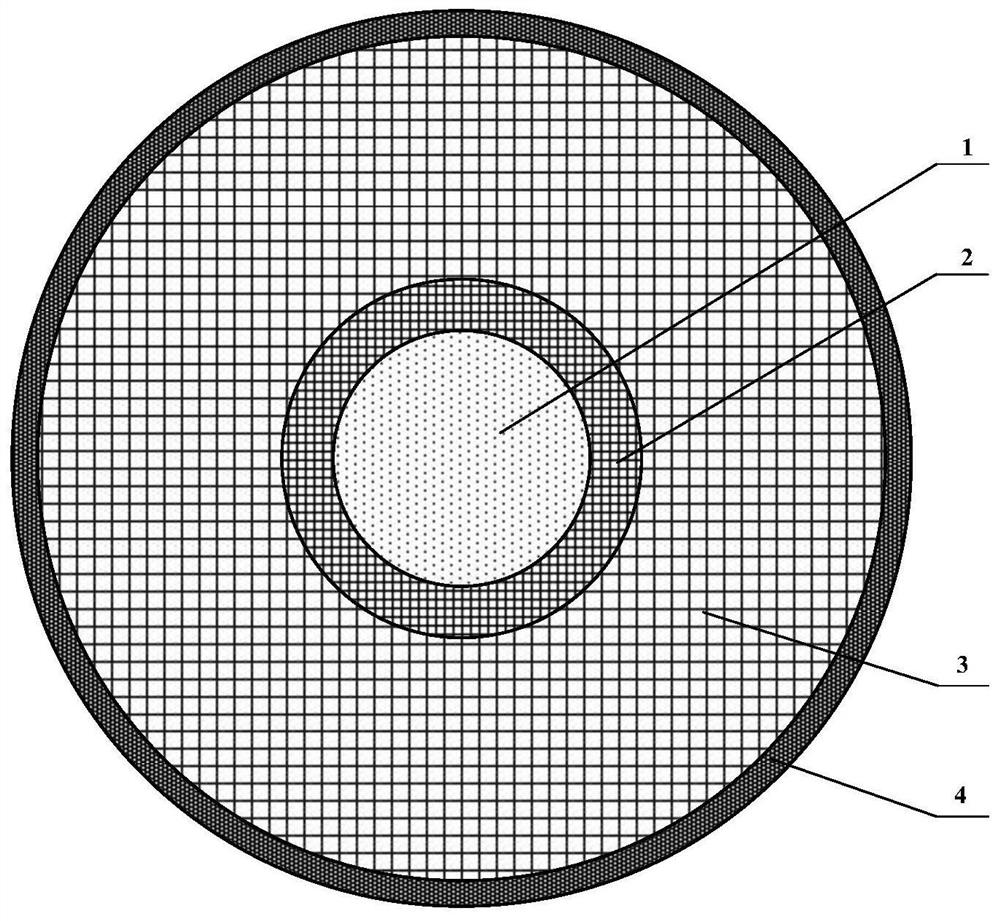
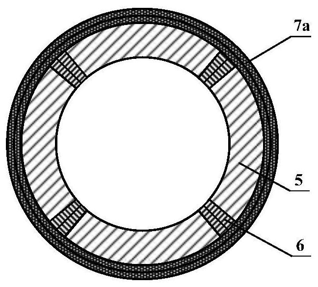
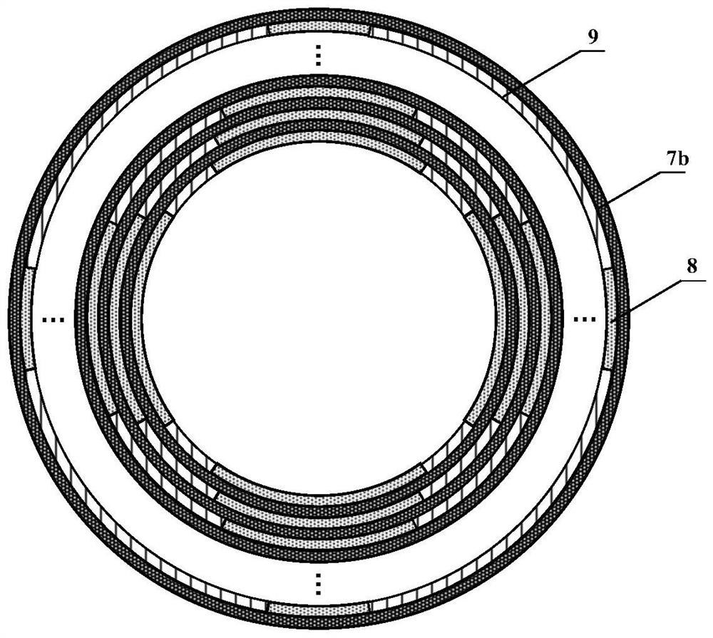
[0025] like figure 1 , Figure 5 and Image 6 , The high speed rotor of a sinusoidal magnetomotive potential distribution, comprises a shaft 1, a sintered permanent magnet section 2, the carbon fiber composite magnetic film unit 3 and the sheath 4 of the rotor; the high-speed permanent magnet motor shaft 1 is located innermost rotor, an outer shaft coaxially sleeved sintered permanent unit 2, the outer sintered permanent unit 2 by an interference fit with the wound carbon fiber composite magnetic film unit 3, and the winding process to ensure that the composition of the magnetic powder and carbon fiber film magnetic film layer 3 block of said magnetic film and a carbon fiber composite subunit composite unit 8 and the geometric centerline sintered permanent magnet block 5 geometric centerline coincides with the carbon fiber composite magnetic film unit 3 is provi...


PUM

PropertyMeasurementUnit
thicknessaaaaaaaaaa
thicknessaaaaaaaaaa
thicknessaaaaaaaaaa

Abstract

The invention discloses a high-speed permanent magnet motor rotor with a sine magnetomotive force distribution rule and a manufacturing method. The high-speed permanent magnet motor rotor comprises arotating shaft, a sintered permanent magnet unit, a magnetic powder adhesive film and carbon fiber composite unit and a rotor sheath which are sequentially arranged from inside to outside in the radial direction, wherein the rotor sheath is formed by multiple layers of carbon fibers III, the magnetic powder adhesive film and carbon fiber composite unit is composed of a plurality of magnetic powderadhesive film and carbon fiber composite subunits, and each magnetic powder adhesive film and carbon fiber composite subunit is composed of a magnetic powder adhesive film layer block, an adhesive film layer block and a carbon fiber layer; and the number of the magnetic powder adhesive film layer blocks and the number of the adhesive film layer blocks are the same as the number of the sintered permanent magnet blocks, and the sum of the polar arc coefficients of the magnetic powder adhesive film layer blocks and the polar arc coefficients of the adhesive film layer blocks is always 1. According to the high-speed permanent magnet motor rotor, the mechanical strength of the motor rotor can be improved, the eddy-current loss of the motor rotor is reduced, and the allowable linear speed of the motor rotor is increased, so that the problems of large eddy-current loss, high temperature rise and low allowable linear speed of the traditional high-speed permanent magnet motor rotor are solved.

Description

Technical field [0001] The present invention is in motor technology, and particularly relates to high speed production methods and the rotor of the sinusoidal distribution of magnetomotive force, the rotor can be used in high speed permanent magnet motor. Background technique [0002] With the rapid development of modern industry, leap advances in aerospace technology, small size, light weight, high power density, high-speed motors and generators have been attached great importance to the International Electrotechnical industry, and has been widely used in many modern industrial applications such as turbo molecular pump, centrifuge, high-speed machine tools, compressors, flywheel energy storage, aerospace and so on. [0003] Due to the permanent magnet motor having a high efficiency and a power factor, a wide range of operating speed and other advantages, especially suitable for high-speed high-performance motor systems, it has become the mainstream of the high-speed motor resear...

Claims


Application Information

Patent Timeline
Patent Type & Authority Applications(China)
IPC IPC(8): H02K1/27H02K1/28H02K15/03
CPCH02K1/27H02K1/28H02K15/03H02K2213/03
Inventor 徐振耀张凤阁于思洋金石刘光伟
Owner SHENYANG POLYTECHNIC UNIV
Why Eureka
Try Eureka