
High-speed signal link design adopting parallel capacitors

A capacitor and parallel technology, applied in the field of radio frequency, can solve the problems of difficulty in realization, large difference in size, degradation of high-speed signal performance, etc., and achieve the effect of unique design and simple production.

Pending Publication Date: 2020-12-04
北京安石科技有限公司
View PDF12 Cites 0 Cited by
  • Summary
  • Abstract
  • Description
  • Claims
  • Application Information

AI Technical Summary

Problems solved by technology

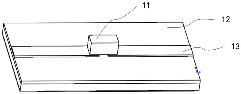
[0003] Under the requirements of ensuring the impedance matching of the PCB12 transmission line, it is often necessary to add design schemes such as series capacitance 11 on the PCB circuit according to the design scheme of the actual circuit and chip, such as figure 1 , in order to realize the effect of cutting off the DC signal and passing the AC signal, similar to a high-pass filter, the size of this capacitor 11 is 0201, 0402 or 0603, etc., and the size of the capacitor is quite different from that of the transmission line 13, and it will be felt when the high-frequency electromagnetic field is transmitted Obvious abrupt change in impedance, resulting in degraded high-speed performance of the signal
In terms of high-speed circuit design, in order to achieve lower-loss signal transmission and the passage of wider frequency signals, it is often necessary to design two capacitors with different capacitances in parallel on the transmission line, but since two capacitors are connected in parallel on the high-speed transmission line It will cause stronger impedance mismatch and signal loss, so this high-speed capacitor parallel design is currently difficult to achieve

Method used


Image

  • High-speed signal link design adopting parallel capacitors
  • High-speed signal link design adopting parallel capacitors
  • High-speed signal link design adopting parallel capacitors

Examples


Embodiment Construction

[0021] The preferred embodiments of the present invention will be described below in conjunction with the accompanying drawings. It should be understood that the preferred embodiments described here are only used to illustrate and explain the present invention, and are not intended to limit the present invention.

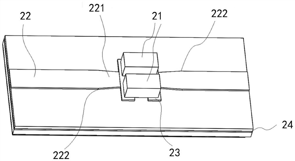
[0022] Based on the current difficulties in high-speed PCB design in the application of parallel capacitors, a design invention for high-speed transmission lines that can be used in parallel capacitors is proposed. like figure 2 , in the structure where two high-speed capacitors 21 are connected in parallel, there is a transmission line 221 with a uniform and gradual width between the transmission line 22 and the capacitor pad 23. At a distance of 230.3-0.6mm from the capacitor pad, the transmission line begins to narrow, and the narrowest part of the transmission line Connect with the capacitor pad 23, the transmission line width at the narrowest point is 60%-80% ...


PUM


Abstract

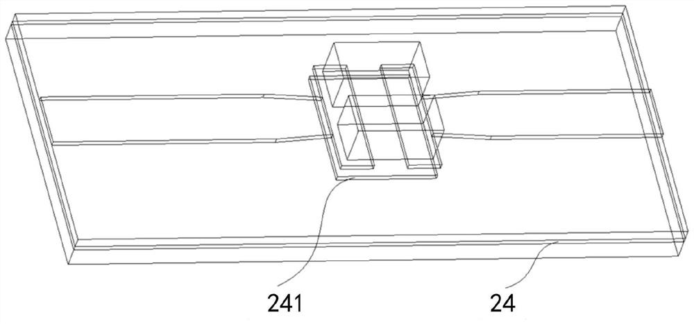
The invention provides a high-speed signal link design adopting parallel capacitors. The link design comprises a parallel capacitor, a parallel capacitor transmission line and a signal backflow layer.The parallel capacitor transmission line is arranged below the parallel capacitor, the parallel capacitor is welded to the parallel capacitor transmission line through a capacitor bonding pad, the backflow layer is arranged below the parallel capacitor transmission line, and the parallel capacitor transmission line comprises a width gradual change part, the width of the transmission line of the part is linearly narrowed from a position which is a certain distance away from the parallel capacitor bonding pad, in addition, the signal backflow layer right below the parallel capacitor is integrally dug out. According to the high-speed signal link design adopting the parallel capacitors, impedance mismatch and signal loss on a transmission line can be avoided.

Description

technical field [0001] The invention relates to the field of radio frequency technology, in particular to a high-speed signal link design using parallel capacitors. Background technique [0002] Driven by the current demand for 5G wireless fronthaul and ultra-large broadband data centers in the fifth-generation communication network, the transmission rate requirements for its core components are getting higher and higher. High frequency, high speed, and high density have gradually become a significant development trend of advanced communication products. one. High-frequency signal transmission and high-speed digitalization force PCBs to move towards micro-holes and buried / blind holes, finer wires, and uniform thinner dielectric layers. High-speed PCB design technology has become an important research field. In high-speed digital circuit systems, if the impedance mismatch of the transmission line will cause data signal reflection, resulting in signal distortion such as overs...

Claims


Application Information

Patent Timeline
Patent Type & Authority Applications(China)
IPC IPC(8): H05K1/16
CPCH05K1/162
Inventor 刘青山
Owner 北京安石科技有限公司
Learn More