
Cable connector assembly including coaxial wires and single core wires

a technology of coaxial wires and connectors, applied in the direction of fixed connections, coupling device connections, printed circuit aspects, etc., can solve the problems of large large soldering volume, and low soldering stability of cables, so as to improve the high-speed signal transmission performance of coaxial lines and reduce the overall volume of cable connector assemblies. , the effect of improving the stability of soldering

Active Publication Date: 2022-05-31
FOXCONN (KUNSHAN) COMPUTER CONNECTOR CO LTD +1
View PDF23 Cites 0 Cited by
  • Summary
  • Abstract
  • Description
  • Claims
  • Application Information

AI Technical Summary

Benefits of technology

[0004]A main object of the present invention is to provide a cable connector assembly, the cable is soldered reliably on the circuit board, and the transmission distance of the coaxial wire on the circuit board is short, thereby increasing the performance of high-speed signal transmission of the coaxial wire, and At the same time the volume of the entire cable connector assembly is small.
[0006]Compared to the prior art, the present invention has the advantage that not only improves the soldering stability, but also improves the high-speed signal transmission performance of the coaxial line, and effectively reduces the overall volume of the cable connector assembly.

Problems solved by technology

The rear side of the circuit board is provided with a soldering pad connected with a cable, the cable includes coaxial wires and a single core wire, the coaxial cable can transmit high-speed signals, all the cables are soldered side by side to the same row of soldering pad on the circuit board, the tight arrangement of cables is easy to cause the possibility of empty soldering, In addition, the signal transmission path on the circuit board is too long, which affects the performance of signal transmission, At the same time, the overall volume of the cable connector assembly is relatively large.

Method used


Image

  • Cable connector assembly including coaxial wires and single core wires
  • Cable connector assembly including coaxial wires and single core wires
  • Cable connector assembly including coaxial wires and single core wires

Examples


Embodiment Construction

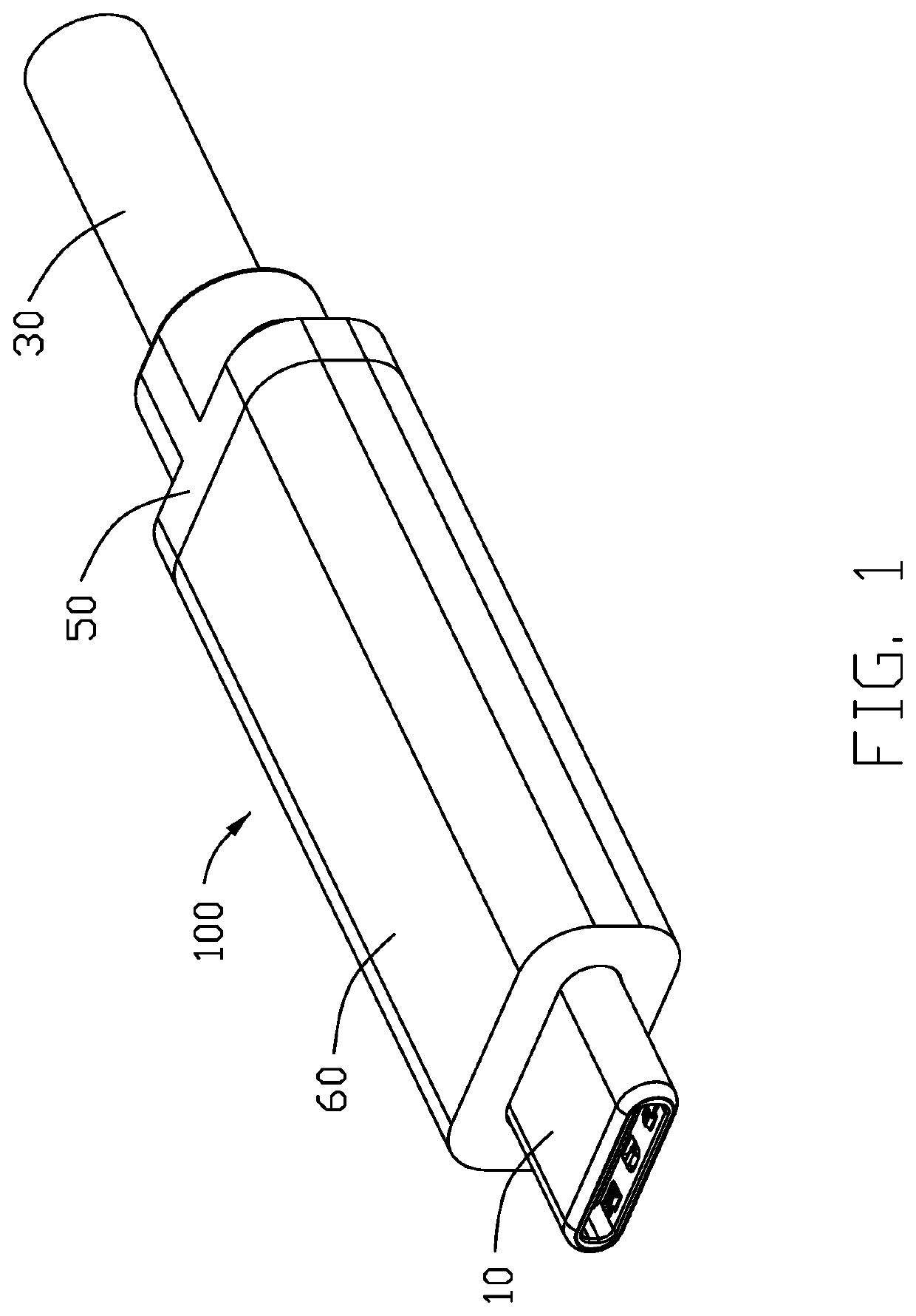
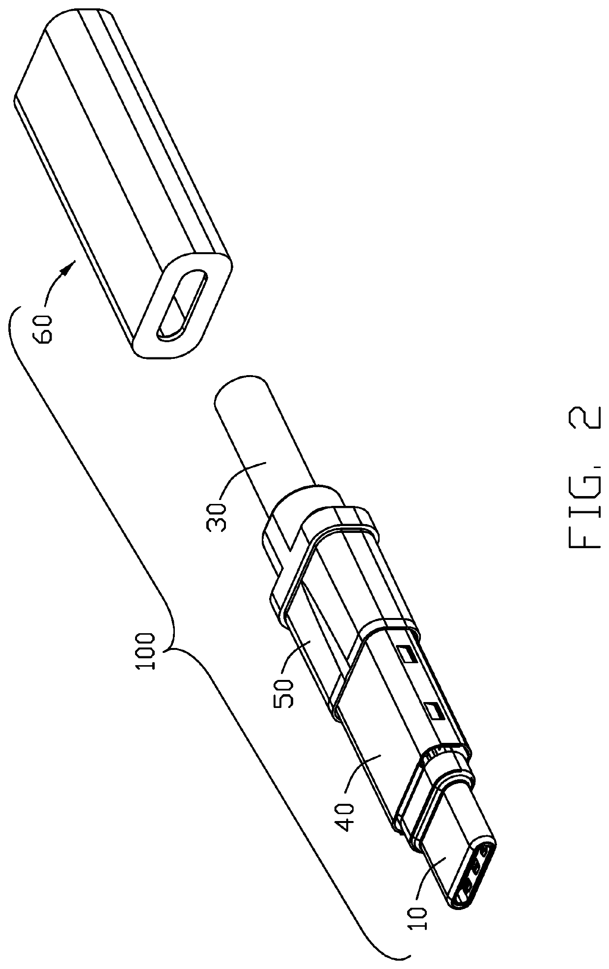
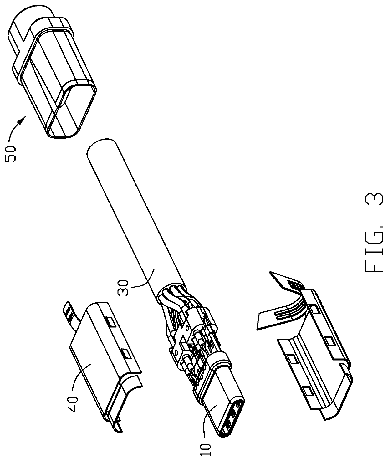
[0017]Referring to FIGS. 1-10, a cable connector assembly 100 of the present invention is shown and can be mated with a mating connector in two orientations. The cable connector assembly 100 comprises an electrical connector 10, a circuit board 20 electrically connected to the electrical connector 10, and a cable 30 electrically connected to the circuit board 20. Also shown are a metal shell 40 covering the rear of the electrical connector 10 and the front of the cable 30 and housed the circuit board 20, an inner mold 50 covering the rear of the metal shell 40 and the front of the cable 30, an insulating hosing 60 provided outside the metal shell 40 and in the front of the inner mold 50, and a cable management block 70 for positioning the cable 30. The cable connector assembly 100 complies with Thunderbolt 3.0 specifications, and the transmission speed of each channel can reach 10 Gbps or even higher.

[0018]The electrical connector 10 includes a front mating end 11, which can be mate...


PUM


Abstract

A cable connector assembly includes: an electrical connector; a circuit board electrically connected to the electrical connector and including a first row of pads and a second row of pads located behind the first row of pads and separated from the first row of pads; and a cable electrically connected to the circuit board and including plural coaxial wires each including a center conductor and a shielding layer and plural single core wires each comprising a conductor; wherein the center conductors of the coaxial wires are soldered to the first row of pads of the circuit board, and the conductors of the single core wires and the shielding layers of the coaxial wires are soldered to the second row of pads of the circuit board.

Description

BACKGROUND OF THE INVENTION1. Field of the Invention[0001]The present invention relates generally to a cable connector assembly, and more particularly to a cable connector assembly containing a circuit board.2. Description of Related Arts[0002]China patent No. CN105702327A (U.S. Pat. No. 9,979,145) discloses a cable connector assembly. The cable connector assembly comprising an electrical connector, a circuit board electrically connected to the electrical connector, and a cable electrically connected to the circuit board. The rear side of the circuit board is provided with a soldering pad connected with a cable, the cable includes coaxial wires and a single core wire, the coaxial cable can transmit high-speed signals, all the cables are soldered side by side to the same row of soldering pad on the circuit board, the tight arrangement of cables is easy to cause the possibility of empty soldering, In addition, the signal transmission path on the circuit board is too long, which affect...

Claims


Application Information

Patent Timeline
Patent Type & Authority Patents(United States)
IPC IPC(8): H01R24/60H01R12/53H01R13/6591H05K1/11H01R13/66H01R107/00
CPCH01R24/60H01R12/53H01R13/6591H01R13/6658H05K1/111H01R2107/00H05K2201/09409H05K2201/10189H01R13/665H01R9/0515H01R12/515H01R4/023H01R13/502H01R43/00H01R43/02H01R13/5812H01R13/6593H01R13/6594H05K2201/09809H05K2201/10356H05K2201/10446H05K1/11H05K3/34
Inventor DONG, YUE-JUNSUN, FENG-JUNCHEN, JUNHSU, YANG-TSUN
Owner FOXCONN (KUNSHAN) COMPUTER CONNECTOR CO LTD
Learn More