
A stamping device for sheet metal processing

A stamping device and technology of sheet metal parts, applied in the field of sheet metal parts processing, can solve the problems of waste materials stuck in the stamping knife, lack of operation protection measures, inconvenient removal of sheet metal parts, etc., so as to avoid material jamming and facilitate unloading Fast and efficient work

Active Publication Date: 2022-07-26
山东维创精密电子有限公司
View PDF0 Cites 0 Cited by
  • Summary
  • Abstract
  • Description
  • Claims
  • Application Information

AI Technical Summary

Problems solved by technology

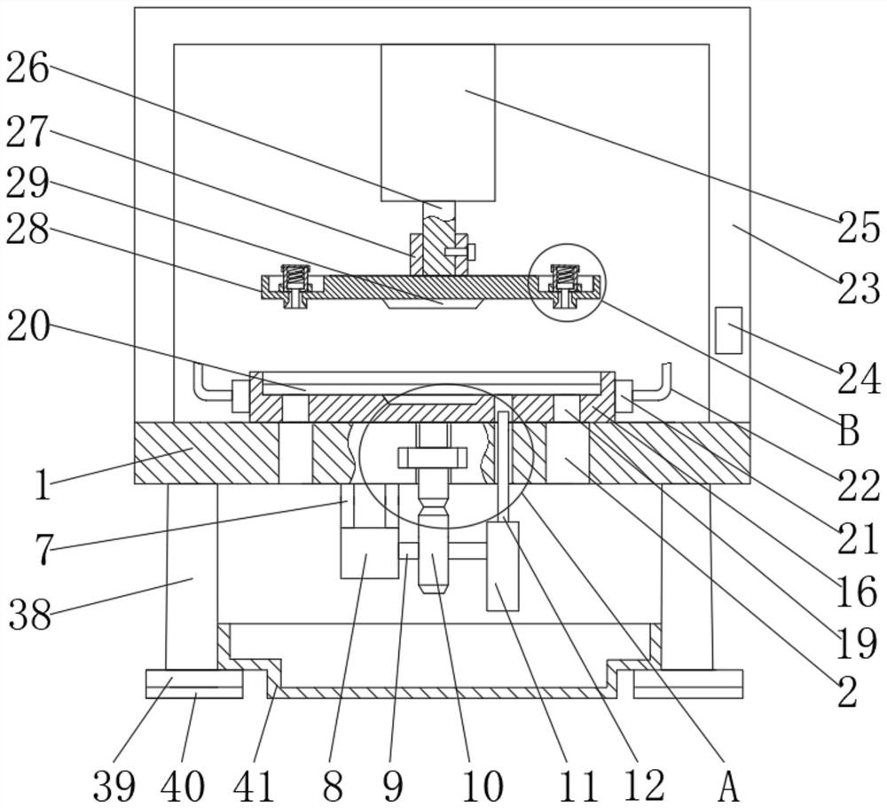
[0004] The purpose of the present invention is to provide a stamping device for sheet metal processing, which solves the problem that the existing sheet metal stamping device lacks operation protection measures, and also solves the problem that only stamping and punching processes can be performed separately, It also solves the problems that it is inconvenient to take out the sheet metal parts in the die base after stamping, the waste material is stuck in the stamping knife during punching, and the lack of preheating during stamping causes the sheet metal parts to easily damage the stamping knife in a low temperature environment

Method used


Image

  • A stamping device for sheet metal processing
  • A stamping device for sheet metal processing
  • A stamping device for sheet metal processing

Examples


Embodiment

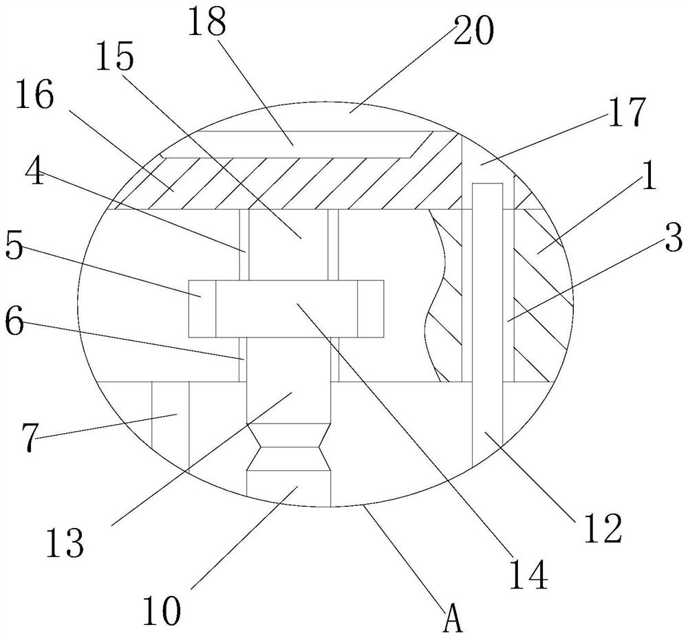
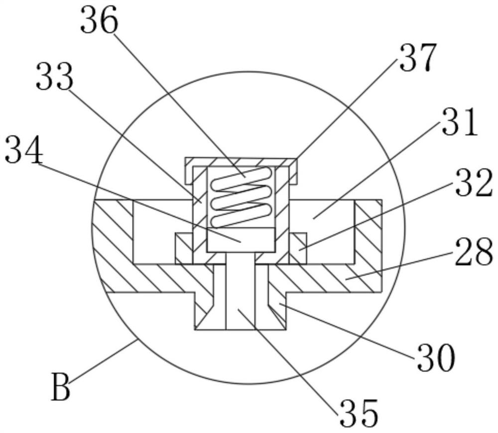
[0034] see Figure 1-7 , a stamping device for sheet metal parts processing, including a support table 1, a discharge chute 2 is opened on the support table 1, a motor frame 7 is fixedly connected to the lower end of the support table 1, and a motor is fixedly installed at the lower end of the motor frame 7 8. It is a servo motor, which belongs to the prior art. The outer side of the rotating shaft 9 of the motor 8 is fixedly installed with a gear 10, the end of the rotating shaft 9 is fixedly installed with a cam 11, and the upper end of the cam 11 is connected to a push rod 12. A rack 13 is engaged, a slider 14 is fixedly connected to the upper end of the rack 13, a connecting block 15 is fixedly connected to the upper end of the slider 14, and a mold base 16 is fixedly connected to the upper end of the connecting block 15, and a groove is opened in the mold base 16 18. A plate 20 is embedded in the die base 16;

[0035] A heater 21 is fixedly installed on the side of the d...


PUM


Abstract

The invention belongs to the field of sheet metal parts processing, and in particular relates to a stamping device for sheet metal parts processing, comprising a support table, a discharge slot is opened on the support table, and a motor frame is fixedly connected to the lower end of the support table, A motor is fixedly installed at the lower end of the motor frame, a gear is fixedly installed on the outer side of the rotating shaft of the motor, a cam is fixedly installed at the end of the rotating shaft, and the upper end of the cam is connected to a push rod, and the upper end of the gear is fixedly installed. Mesh with a rack. In the present invention, a moving mechanism composed of a connecting block, a slider and a rack is designed at the bottom of the die base, and driven by a motor and a gear, and a proximity switch is also installed on the support table, so that the die base can be stopped at a designated position, and when the need arises During the feeding and unloading process, the motor can drive the die base to move forward, so that the die base leaves the lower part of the stamping die, so as to realize the protection during loading and unloading, and ensure the safety of the staff.

Description

technical field [0001] The invention relates to the technical field of sheet metal parts processing, in particular to a stamping device used for sheet metal parts processing. Background technique [0002] Sheet metal parts are the products processed by the sheet metal process, and we are inseparable from sheet metal parts everywhere in our lives. Sheet metal parts are made by filament power winding, laser cutting, heavy duty machining, metal bonding, metal drawing, plasma cutting, precision welding, roll forming, sheet metal bending, die forging, water jet cutting, precision welding . [0003] During the processing of sheet metal parts, many processes such as blanking, punching, stamping, welding, and drawing are required. When punching and punching, it generally needs to be carried out step by step, and when punching and punching, the workpiece is located under the punching device. Once a failure occurs during operation, it may cause the punching device to be damaged when...

Claims


Application Information

Patent Timeline
Patent Type & Authority Patents(China)
IPC IPC(8): B21D35/00B21D55/00B21D45/02B21D37/16B21D37/10B21D37/12
CPCB21D35/001B21D55/00B21D45/02B21D37/16B21D37/10B21D37/12
Inventor 李成瑶杨兰明
Owner 山东维创精密电子有限公司
Learn More