
Steel damping shock absorption and isolation support

A technology of steel damping, vibration reduction and isolation, which is applied to bridge parts, bridges, buildings, etc., can solve the problems of large difference in the fuse force of the support, affect the deformation of the steel damping component, and the unstable connection, etc., to meet the design requirements , economical and practical, with obvious effects

Pending Publication Date: 2020-12-08
TONGJI UNIV
View PDF1 Cites 3 Cited by
  • Summary
  • Abstract
  • Description
  • Claims
  • Application Information

AI Technical Summary

Problems solved by technology

However, the arc structure added in the middle of the ring part of the damping support will affect the deformation of the steel damping component, which cannot match the ring structure well, and the entire steel damping part is prone to local damage during the deformation process; each small The ring components need to be connected by steel strands, which is very complicated in actual engineering and the connection is extremely unstable; each ring needs to be connected in series with an anti-buckling rod. Since the length of the anti-buckling rod is long, the required cross-section is will be large, which is unreasonable in engineering design; if the shear pins with limited capacity are scattered in the slideway, it is difficult to control the shear pins to be sheared at the same time due to the tolerance problem, which will cause the actual support There is a large difference between the fusing force and the design fusing force, and at the same time, the capacity is limited. After the shear pin breaks the ring, its fracture can easily hinder the normal sliding of the slideway

Method used


Image

  • Steel damping shock absorption and isolation support
  • Steel damping shock absorption and isolation support
  • Steel damping shock absorption and isolation support

Examples


Embodiment 1

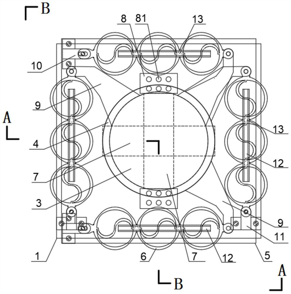
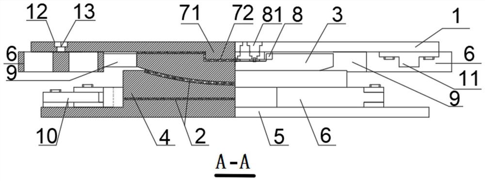
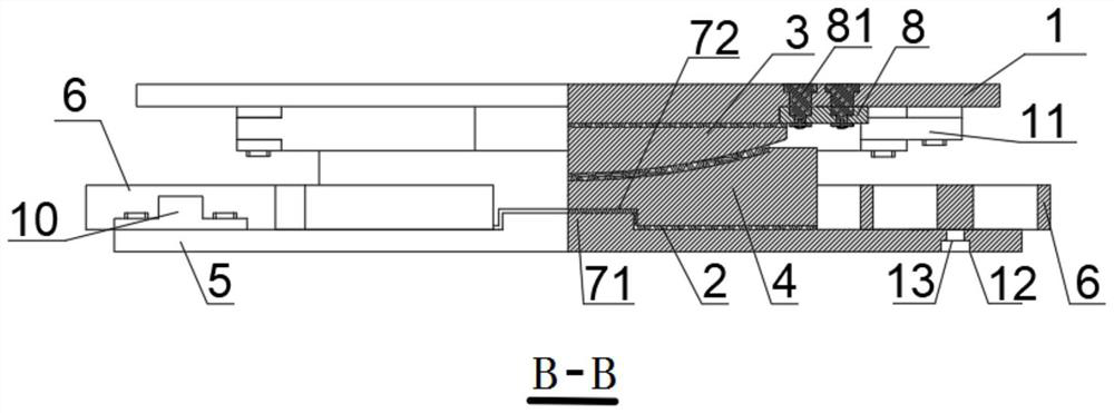
[0046] Such as figure 1 , figure 2 , image 3 , Figure 4 , Figure 5 , Figure 6 and Figure 7 As shown, a function-controllable one-way movable steel damping and shock-absorbing support mainly includes an upper top plate 1, a spherical crown 3, a middle lining plate 4, a lower bottom plate 5, an upper top plate 1, a spherical crown 3, and a spherical crown 3. There is a sliding friction pair 2 between the middle lining plate 4, the middle lining plate 4 and the lower bottom plate 5, and a directional slideway 7 is set between the top plate 1 and the ball cap 3, the middle lining plate 4 and the bottom plate 5, and the support Steel damping parts 6 are provided in front, rear and left and right.

[0047] The directional slideway 7 between the upper top plate 1 and the ball cap 3 is made up of a chute 72 and a slide rail 71, the slide rail 71 is connected with the upper top plate 1, the chute 72 is located on the ball cap 3, and the slide rail 71 and the chute 72 is pr...

Embodiment 2

[0052] Such as Figure 8 , Figure 9 and Figure 10 As shown, a function-controllable fixed steel damping shock-absorbing support mainly includes an upper top plate 1, a spherical crown 3, a middle lining plate 4, a lower bottom plate 5, an upper top plate 1 and a spherical crown 3, a spherical crown 3 and a middle Sliding friction pairs 2 are arranged between the liner 4, the middle liner 4 and the lower bottom plate 5, wherein the top plate 1 and the spherical cap 3, the middle liner 4 and the bottom plate 5 are provided with directional slides 7, and the front, rear, left and right sides of the support Steel damping parts 6 are all provided.

[0053] The directional slideway 7 between the upper top plate 1 and the ball cap 3 is made up of a chute 72 and a slide rail 71, the slide rail 71 is connected with the upper top plate 1, the chute 72 is located on the ball cap 3, and the slide rail 71 and the chute 72 is provided with a sliding friction pair 2, the direction of th...

Embodiment 3

[0058] Such as Figure 11 , Figure 12 and Figure 13 As shown, a function-controllable two-way movable steel damping and shock-absorbing support mainly includes an upper top plate 1, a spherical crown 3, a middle lining plate 4, a lower bottom plate 5, an upper top plate 1 and a spherical crown 3, and a spherical crown 3 and Between the middle liner 4, the middle liner 4 and the lower bottom plate 5, there is a sliding friction pair 2, in which the top plate 1 and the ball cap 3, the middle liner 4 and the bottom plate 5 are provided with a directional slideway 7, in the front and back of the support and Steel damping parts 6 are arranged on the left and right sides.

[0059] The directional slideway 7 between the upper top plate 1 and the ball cap 3 is made up of a chute 72 and a slide rail 71, the slide rail 71 is connected with the upper top plate 1, the chute 72 is located on the ball cap 3, and the slide rail 71 and the chute 72 is provided with a sliding friction pai...


PUM


Abstract

The invention relates to a steel damping shock absorption and isolation support which comprises an upper top plate, a spherical crown, a middle lining plate and a lower bottom plate which are sequentially arranged from top to bottom. Sliding friction pairs are arranged between the upper top plate and the spherical crown, between the spherical crown and the middle lining plate and between the middle lining plate and the lower bottom plate; and directional slideways and steel damping parts are arranged between the upper top plate and the spherical crown and between the middle lining plate and the lower bottom plate. Compared with the prior art, under the normal operation condition of a bridge, the steel damping shock absorption and isolation support meets the requirement for free stretchingand retracting of a main beam under the action of variable loads such as temperature; when an earthquake comes, pins are cut off, limiting check blocks at the two sides of the directional slideways fail, the earthquake force borne by fixed piers is not increased any more, and therefore the shock insulation effect is achieved; and meanwhile, steel damping components on the piers play a role, the earthquake force is dissipated through reciprocating motion of the steel damping components, and excessive relative displacement of pier beams is prevented. The steel damping shock absorption and isolation support is simple in structure, obvious in effect, economical, practical and capable of meeting the product design requirement.

Description

technical field [0001] The invention belongs to the technical field of shock absorbing and isolating components for bridge engineering, and relates to a steel damping and shock absorbing support. Background technique [0002] Bearings are functional components that connect bridge girders and piers. The fixed support can realize the displacement constraint on the main girder under the normal use condition of the bridge; the movable support can satisfy the expansion and contraction of the main girder under the normal use condition. In a simply supported girder bridge, one end of the girder uses a fixed support and the other end uses a movable support; in a continuous girder bridge, only one pier in a link uses a fixed support, and the rest of the piers are arranged with movable supports. [0003] Under the action of earthquake load, since the movable pier has no connection device, there will be a large relative displacement of the pier beam, and most of the seismic force is b...

Claims


Application Information

Patent Timeline
IPC IPC(8): E01D19/04
CPCE01D19/042E01D19/046
Inventor 王君杰刘猛
Owner TONGJI UNIV
Learn More