A lubricating element used for drag reduction in water-containing heavy oil production and transportation in wellbore

A heavy oil and component technology, applied in the field of heavy crude oil production, transportation and drag reduction, can solve problems such as affecting oil well production, failing to achieve viscosity reduction effect, heating depth limitation, etc., reducing surface water treatment facilities and reducing surface gathering and transportation. Cost, effect of reducing flow resistance

Active Publication Date: 2021-04-02
SOUTHWEST PETROLEUM UNIV
View PDF6 Cites 0 Cited by
  • Summary
  • Abstract
  • Description
  • Claims
  • Application Information

AI Technical Summary

Problems solved by technology

However, the traditional heavy oil drag reduction process has some shortcomings: the cost of adding a viscosity reducer is high, and the oil field needs to prepare it according to its own actual situation; the thin oil needs to consume thin oil resources, and when the water content of the oil well reaches a certain amount, the produced fluid Inverted emulsification will occur, resulting in the failure to achieve the ideal viscosity reduction effect; the mixing of sewage will cause the production fluid to fail to form a uniform oil-in-water emulsion, which will not achieve the ideal viscosity reduction effect, and the sewage contains impurities. Too much water will pollute the oil layer, affect the production of the oil well, and cause oilfield losses; the operation cost of electric heating is high, and it is easily affected by various factors. The heating depth in the wellbore is limited to a certain extent, and the high salinity formation water will shorten the electric heating. tool life

Method used


Image

  • A lubricating element used for drag reduction in water-containing heavy oil production and transportation in wellbore
  • A lubricating element used for drag reduction in water-containing heavy oil production and transportation in wellbore
  • A lubricating element used for drag reduction in water-containing heavy oil production and transportation in wellbore

Examples


Embodiment Construction

[0017] The present invention will be further described in detail below in conjunction with the accompanying drawings and specific embodiments.

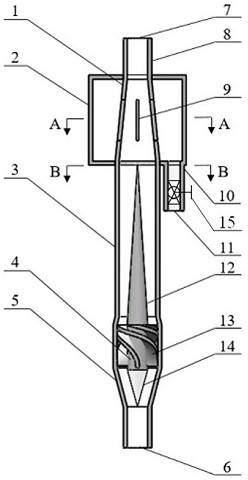
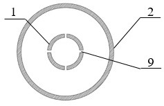
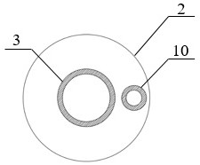
[0018] The invention provides a lubricating element for reducing drag in the production and transportation of water-containing heavy oil in the wellbore, comprising: a middle rod (4), guide vanes (13), a central cone (12) and a steady flow cone (14) The guide part is a casing part made up of a liquid inlet pipe (5), a swirl pipe (3), an outlet pipe (1), a drain chamber (2), a drain pipe (10) and a ring pipe (8). Specifically, the appearance of the liquid inlet pipe (5) is funnel-shaped, the end with a larger diameter is connected to the swirl pipe (3), and the end with a smaller diameter is connected to the upstream collection and transportation pipe; there is a section in the middle of the swirl pipe (3). The diameter of the pipe is tapered, which can not only prevent the guide part from sliding into the outlet pipe (1) during the as...


PUM


Abstract

The invention relates to a lubricating element used for drag reduction in the production and transportation of water-containing heavy oil in a wellbore. The lubricating element is composed of a flow guiding part and a casing part; The rod connects and fixes the central cone, steady flow cone and guide vane. The oil-water mixture converts the axial velocity part into a tangential velocity through the guide vane for swirl separation. The central cone gathers the dispersed oil phase in the mixture and forms The upward-flowing columnar oil core acts as the central fluid of the annular flow, and the water phase is thrown to the wall of the swirl tube to rotate upwards, and part of the water collects in the drainage cavity through the strip-shaped water outlet holes, and then flows from the drain outlet at the bottom of the drainage cavity. After being discharged, it is re-injected into the formation, and the remaining water wraps the oil flow as a water ring, which acts as a lubricant for the fluid-solid interface and realizes cold recovery of heavy oil; the invention belongs to a static component, and has three functions of oil-water separation, water control and liquid ring formation. Integrated, not only reduces the energy consumption of heavy crude oil production and transportation, but also reduces the surface water treatment facilities.

Description

technical field [0001] The invention relates to a lubricating element used for drag reduction in water-containing heavy oil production and transportation in a wellbore, and belongs to the technical field of drag reduction in heavy crude oil production and transportation. Background technique [0002] As a special crude oil, heavy oil contains a large amount of colloid and asphaltene, and has the characteristics of high density, high viscosity, and poor fluidity, resulting in large pipeline pressure loss and cumbersome process during its exploitation and gathering and transportation. The supporting processing facilities are complicated, and the maintenance and operation costs are high. In the reservoir environment, the fluidity of water-bearing heavy oil is relatively good, but after the heavy oil flows into the wellbore, the temperature will gradually decrease during the lifting process of the heavy oil, resulting in an increase in the flow resistance of the heavy oil and ma...

Claims


Application Information

Patent Timeline
Patent Type & Authority Patents(China)
IPC IPC(8): E21B43/16E21B43/40E21B34/06
CPCE21B43/16E21B43/40E21B34/06E21B43/385E21B43/127E21B43/20
Inventor 敬加强黄婉妮
Owner SOUTHWEST PETROLEUM UNIV
Why Eureka
Try Eureka