Burner and W flame boiler

A technology of burners and secondary air, which is applied in the direction of burners, burners for burning powder fuel, and combustion methods, etc. It can solve the problems of pulverized coal ignition, unfavorable burnout, large amount of desuperheating water, and direct heating of pulverized coal. Achieve the effects of being conducive to ignition and stable combustion, increasing the heating area, and improving utilization

Pending Publication Date: 2020-12-08
TRANSTEK IND HK LTD KOWLOON
View PDF0 Cites 0 Cited by
  • Summary
  • Abstract
  • Description
  • Claims
  • Application Information

AI Technical Summary

Problems solved by technology

The slit-type burner has a low primary wind speed, and the pulverized coal is mainly driven downward by the high-speed secondary air, which cannot solve the problem of high NOx concentration caused by premature mixing of pulverized coal and a large amount of secondary air; double cyclone pulverized coal The condensed burner has insufficient flame downstroke ability, and cannot make good use of the lower furnace space to organize combustion, which may easily cause the problems of high carbon content in boiler fly ash and large amount of cooling water. In order to solve these problems, we can only choose to add Large secondary air volume, but it will increase the NOx emission value at the outlet of the boiler economizer, it is difficult to control the NOx emission value at a low level while taking into account the boiler efficiency; double air-adjusting concentrated swirl burner, two-layer swirl The design of the secondary air effectively solves the downshooting ability of the flame, but the pulverized coal airflow is located in the "shielding" of the two strong and thick airflows of the internal and external secondary air, and it is difficult for the returning high-temperature flue gas to directly heat the pulverized coal , which is unfavorable to the ignition and burnout of pulverized coal, and the carbon content of fly ash is relatively high

Method used


Image

  • Burner and W flame boiler
  • Burner and W flame boiler

Examples


Embodiment Construction

[0020] The present invention will be further described in detail below in conjunction with the accompanying drawings, so that those skilled in the art can implement it with reference to the description.

[0021] It should be understood that terms such as "having", "comprising" and "including" used herein do not exclude the presence or addition of one or more other elements or combinations thereof.

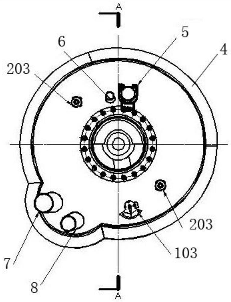
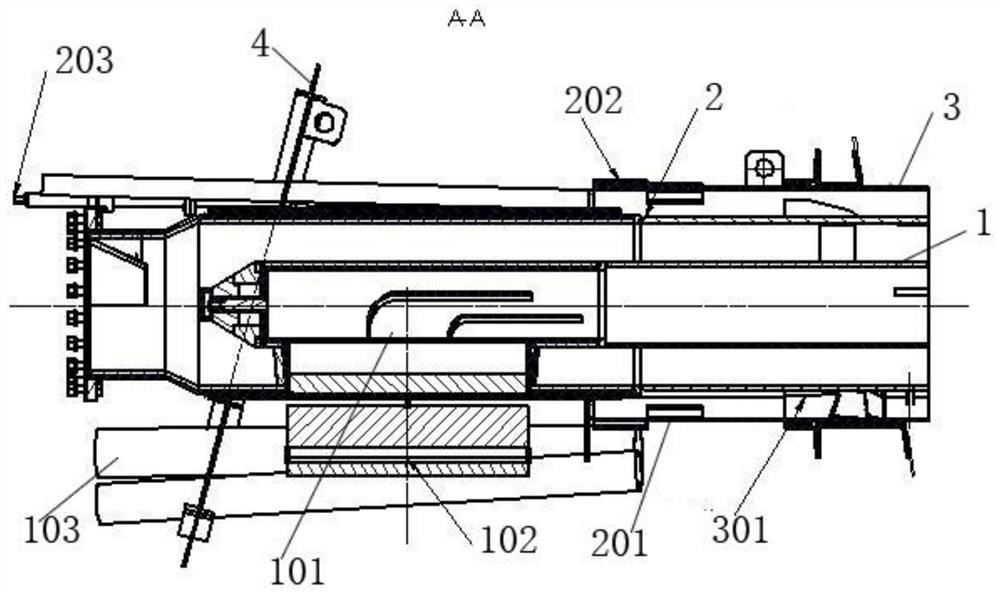
[0022] Such as figure 1 , 2 As shown, the embodiment of the present application provides a burner, including a central secondary air pipeline 1, a pulverized coal pipeline 2 and an outer ring secondary air pipeline 3, the central secondary air pipeline 1, the pulverized coal pipeline 2 and The outer ring secondary air duct 3 is set sequentially from the inside to the outside, the central secondary air duct 1 is used to spray the central secondary air, and the pulverized coal pipeline 2 and the central secondary air duct 1 The gap between them is used to spray out the pulverized c...


PUM


Abstract

The invention discloses a burner. The burner comprises a central secondary air pipeline, a pulverized coal pipeline and an outer ring secondary air pipeline; the central secondary air pipeline, the pulverized coal pipeline and the outer ring secondary air pipeline are sequentially arranged in a sleeved manner from inside to outside; the central secondary air pipeline is used for spraying central secondary air; a gap between the pulverized coal pipeline and the central secondary air pipeline is used for spraying pulverized coal airflow; a gap between the outer ring secondary air pipeline and the pulverized coal pipeline is used for spraying outer ring secondary air; and the pulverized coal airflow is located between the central secondary air and the outer ring secondary air. The invention further provides a W flame boiler. According to the burner and the W flame boiler, the relatively high burning efficiency can be guaranteed while the NOx generation amount is reduced.

Description

technical field [0001] The invention relates to the technical field related to W flame boilers. More specifically, the present invention relates to a burner. Background technique [0002] There are many types of W-flame boiler burners in my country, mainly including slit burners, double-adjusting air-concentrating swirl burners, and double-cyclone pulverized coal concentrated burners. The slit-type burner has a low primary wind speed, and the pulverized coal is mainly driven downward by the high-speed secondary air, which cannot solve the problem of high NOx concentration caused by premature mixing of pulverized coal and a large amount of secondary air; double cyclone pulverized coal The condensed burner has insufficient flame downstroke ability, and cannot make good use of the lower furnace space to organize combustion, which may easily cause the problems of high carbon content in boiler fly ash and large amount of cooling water. In order to solve these problems, we can on...

Claims


Application Information

Patent Timeline
Patent Type & Authority Applications(China)
IPC IPC(8): F23C7/00F23D1/00F23L9/00F23N3/00
CPCF23C7/00F23D1/00F23L9/00F23N3/007
Inventor 张庆王颖侯丙军
Owner TRANSTEK IND HK LTD KOWLOON
Why Eureka
Try Eureka