A regenerator coupled with miniature heat pipes and its working method

A micro-sized, recuperator technology, applied in superheaters, indirect heat exchangers, lighting and heating equipment, etc., can solve problems such as the use of regenerators that have not been seen

Active Publication Date: 2021-05-18
CHINA UNIV OF MINING & TECH
View PDF7 Cites 0 Cited by
  • Summary
  • Abstract
  • Description
  • Claims
  • Application Information

AI Technical Summary

Problems solved by technology

At present, the application fields of heat pipes involve aerospace, construction, automobile, radiator manufacturing, medical and health and many other fields, but they are rarely used in the heat recovery technology of Stirling machine, and there is no use of heat pipes for heat recovery. Literature and Reports

Method used


Image

  • A regenerator coupled with miniature heat pipes and its working method
  • A regenerator coupled with miniature heat pipes and its working method
  • A regenerator coupled with miniature heat pipes and its working method

Examples


Embodiment 1

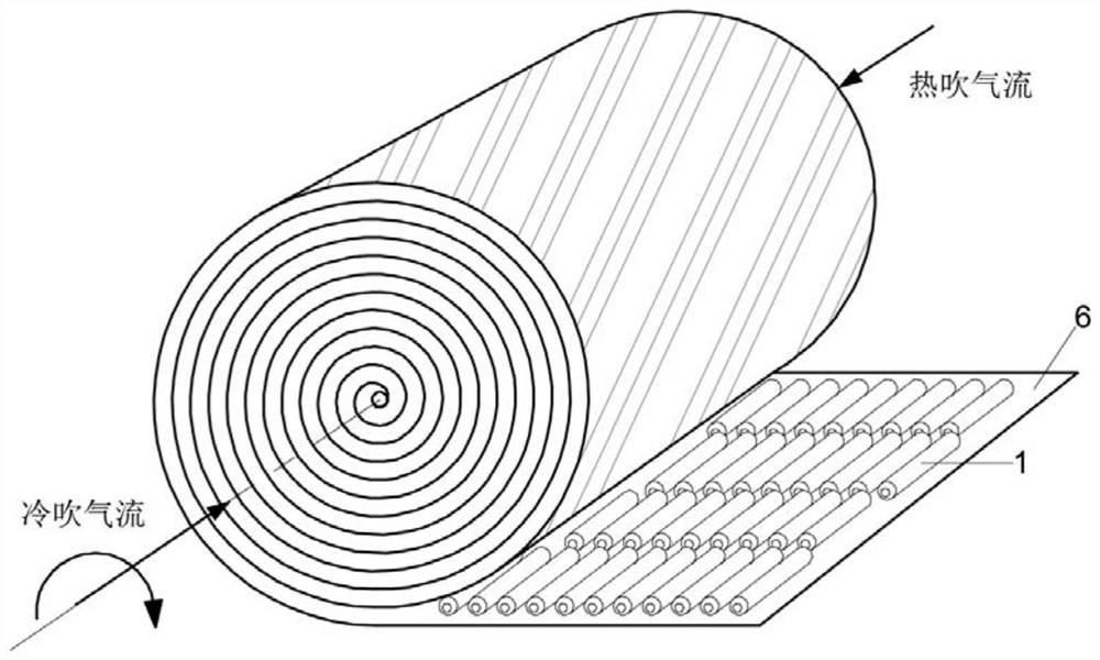
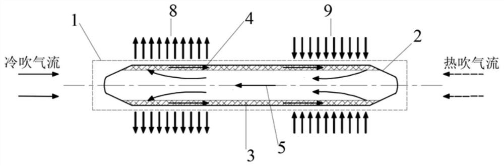
[0047] Such as image 3 As shown, the miniature heat pipe 1 includes a tube shell, a heat pipe capillary structure 3 and a liquid phase change working medium 4. The tube shell tube length is preferably 30 mm, the tube diameter is 3 mm, the tube wall thickness is 0.2 mm, and the axial center distance is 4 mm. The interval between segments is 4mm. The tube shell is made of seamless metal material with high thermal conductivity, which plays a role in quickly transferring heat. The capillary structure 3 of the heat pipe is composed of several layers of fine copper mesh arranged on the inner wall of the heat pipe, and the capillary holes between the multilayer meshes are used to guide the liquid. The liquid phase-change working medium 4 is composed of organic or inorganic substances with a boiling point of 300K-700. Such as Figure 5 Shown is a partial schematic diagram of the staggered arrangement of heat pipes. In the heat blowing stage of the heat recovery process, the high-t...

Embodiment 2

[0049] Such as Figure 8 As shown, the miniature heat pipe 1 is a triangular tube (the triangular tube means that the cross section of the heat pipe is a triangle), including a tube shell and a liquid phase change working medium 4, the length of the heat pipe is preferably 30 mm, and the equilateral length of the triangle is 3 mm. The wall thickness is 0.2mm, the axial center distance is 4mm, and the interval between segments is 4mm. The tube shell is made of seamless metal material with high thermal conductivity, which plays a role in quickly transferring heat. The capillary structure 3 of the heat pipe is composed of sharp-angle grooves on the inner wall of the triangular tube, and uses the capillary suction of the sharp corners to guide liquid. The liquid phase-change working medium 4 is composed of organic or inorganic substances with a boiling point of 300K-700. Figure 6Shown is a partial schematic diagram of the staggered arrangement of triangular heat pipes. In the h...


PUM


Abstract

The invention discloses a regenerator coupled with miniature heat pipes and a working method, which are suitable for use in cold and hot cycle working conditions of industrial and mining enterprises. It includes a columnar structure regenerator, the regenerator is rolled by a rectangular sweeping plate, and the entire surface of the sweeping plate curled inward is provided with a plurality of micro-miniature heat pipes in a staggered arrangement, and the rolling direction of the sweeping plate is consistent with that of the micro-miniature heat pipes. The axial direction is vertical, the gap between two adjacent micro heat pipes in each row of micro heat pipes is equal, and the micro heat pipes in the two adjacent rows of micro heat pipes are staggered to ensure that the first row of micro heat pipes The tail end of the regenerator just corresponds to the gap of the second row of micro-miniature heat pipes; when in use, one end of the regenerator is set at the end for the inflow of high-temperature gas working fluid, and the other end is set at the end for inflow of low-temperature gas working fluid. The heat recovery efficiency is high, the flow resistance inside the regenerator can be significantly reduced, the structure of the regenerator can be made more compact, and thus the cycle efficiency can be significantly improved.

Description

technical field [0001] The invention relates to a regenerator and a working method, in particular to a regenerator coupled with miniature heat pipes and a working method used in industrial and mining enterprises in cold and heat cycle working conditions. Background technique [0002] The Stirling cycle is the basic working principle of Stirling engines and refrigerators. This cycle is a closed generalized Carnot cycle that adopts heat recovery under constant volume and is the most perfect thermodynamic theory. The Stirling cycle is a reversible cycle consisting of two constant-volume endothermic processes and two constant-temperature expansion processes. Ideally, the heat released by the constant-volume exothermic process is just absorbed by the constant-volume endothermic process. The regenerator is the place where the circulating working fluid performs this reheating process. The more complete the reheating process, the higher the thermal efficiency of the heat engine or r...

Claims


Application Information

Patent Timeline
Patent Type & Authority Patents(China)
IPC IPC(8): F25B9/14F25B40/06F28D15/04
CPCF25B9/14F25B40/06F28D15/046F28D2015/0225
Inventor 王焕光张碧林刘猛汤雨明包云皓朱帅
Owner CHINA UNIV OF MINING & TECH
Why Eureka
Try Eureka