
Bearing assembly high-size detection instrument

A technology for dimension detection and bearing assembly, applied in instruments, measuring devices, optical devices, etc., can solve problems such as slipping easily, achieve the effects of reducing slipping, improving pass rate, and reducing processing costs

Inactive Publication Date: 2020-12-08
C&U CO LTD +1
View PDF15 Cites 3 Cited by
  • Summary
  • Abstract
  • Description
  • Claims
  • Application Information

AI Technical Summary

Problems solved by technology

[0004] Aiming at the deficiencies of the prior art, the present invention provides a detection instrument for the high dimension of bearing assembly, which solves the problem in the prior art that the detection of the high dimension of the bearing assembly is slightly larger than the real data, which causes the bearing to slip easily during use due to assembly errors, and improves the detection Accuracy, reducing high dimensional errors in assembly, avoiding bearing slippage affecting the system where it is located

Method used


Image

  • Bearing assembly high-size detection instrument
  • Bearing assembly high-size detection instrument
  • Bearing assembly high-size detection instrument

Examples


Embodiment 1

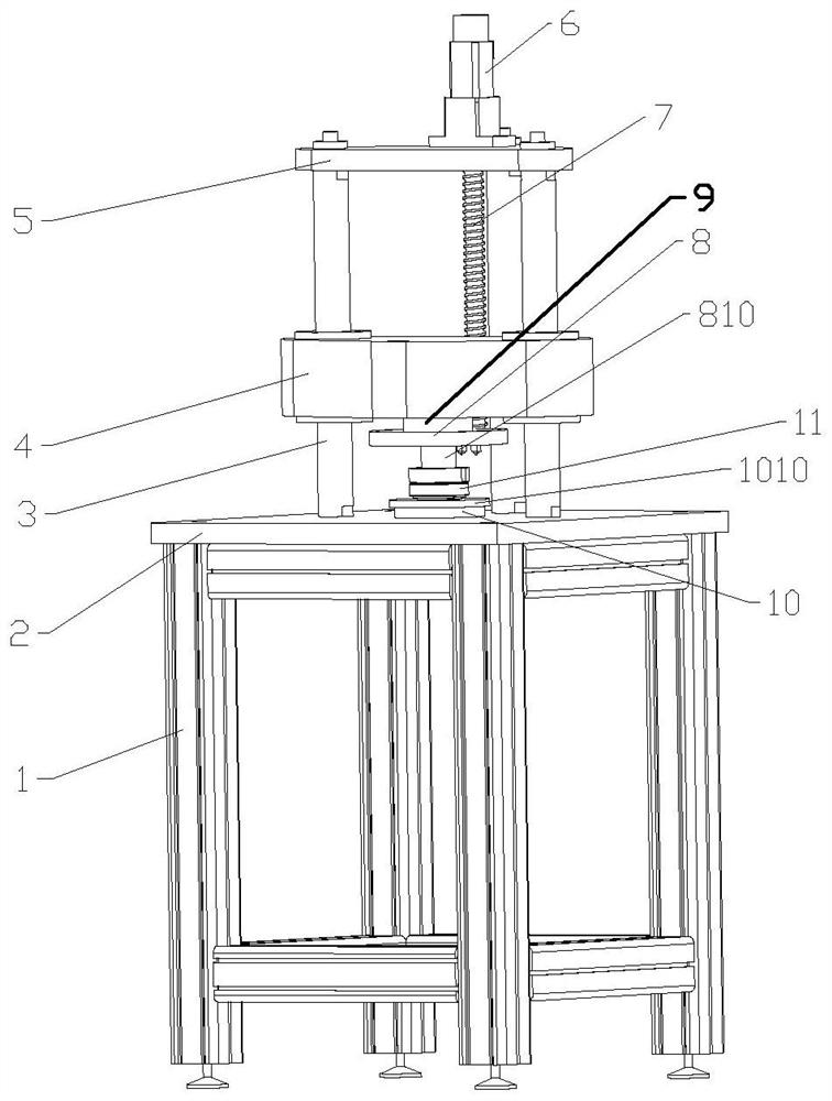
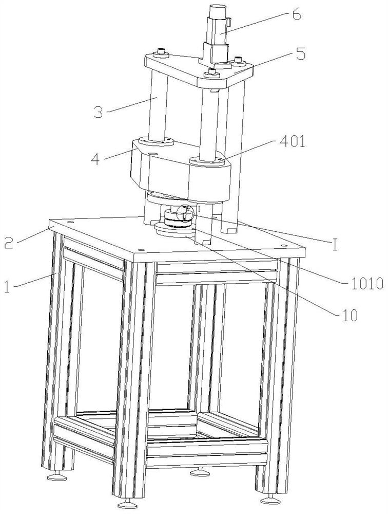
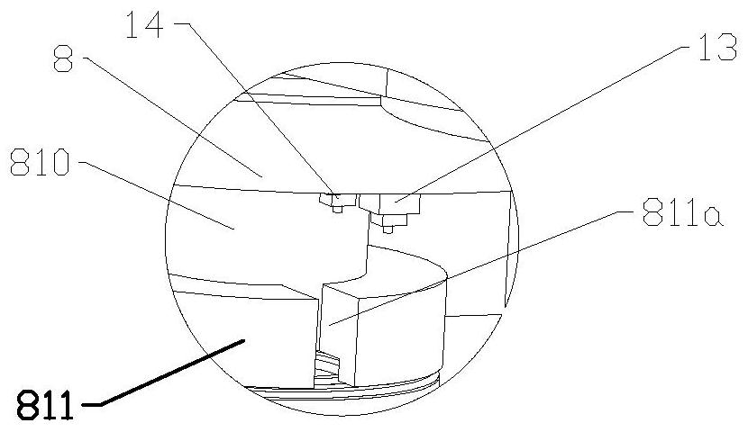
[0026] Embodiment 1 This embodiment provides a high-dimensional detection instrument for bearing assembly, including a detection platform 2, an upper tooling 810 and a lower tooling 1010 set oppositely, an upper tooling seat 8 and a lower tooling seat 10, a pressure sensor 9, a loading platform 4, Install the platform 5, the first ranging detection sensor and the second ranging detection sensor. A support 1 is provided at the bottom of the detection platform 2, and the support 1 has a certain height to raise the detection platform 2 to a designated processing height. The center of the detection platform 2 is provided with a threaded groove, and the lower end of the lower tool seat 10 is a threaded connection end protruding downwards and is fixed in the detection platform 2 by rotating connection. The upper end of the lower tooling base 10 is provided with a positioning shaft 1001 protruding upwards, and the center of the lower tooling 1010 is provided with an opening suitable ...

Embodiment 2

[0044] Embodiment 2 The difference between this embodiment and Embodiment 1 is that the first ranging sensor 13 and the second ranging sensor 14 are sensors with a data display function, and the pressure sensor 9 is also a sensor with a data display function. sensor. In this embodiment, the output end of the pressure sensor 9 is directly connected to the controller of the servo motor 6 . The controller of the servomotor 6 autonomously controls the work of the servomotor 6 according to the data detected by the pressure sensor 9 and preset values ​​and programs. When the applied load reaches the target value, the loading platform 4 stops moving, and the readings of the first distance measuring sensor 13 and the second distance measuring sensor 14 are manually read and calculated.


PUM


Abstract

The invention provides a bearing assembly high-size detection instrument, which belongs to the field of bearing detection, and comprises a detection platform, an upper tool, a lower tool, a pressure sensor, a linear actuator and a loading platform. The lower tool is arranged on the detection platform, the loading platform vertically slides on the detection platform, and the loading platform is driven by the linear actuator. The upper tool is arranged at the bottom of the loading platform, and the pressure sensor is located between the upper tool and the loading platform. A first distance detection sensor and a second distance detection sensor are further arranged at the bottom of the loading platform, the detection end of the first distance detection sensor is arranged downwards and is opposite to the upper end face of a to-be-detected bearing placed on the lower tool, and the detection end of the second distance detection sensor is arranged downwards and is opposite to the upward endface of the lower tool located on the same horizontal plane with the lower end face of the to-be-detected bearing. According to the invention, the assembly high-size measurement difference caused by small axial load can be avoided, the qualified rate of a bearing is improved, and the processing cost is reduced.

Description

technical field [0001] The invention relates to the field of bearing detection, in particular to a bearing assembly height detection instrument. Background technique [0002] In actual working conditions, the tapered roller bearing needs to be preloaded axially to avoid bearing slipping failure due to too small preload. Therefore, the high dimension of the tapered roller bearing assembly has a significant impact on the entire system during actual application. to a vital role. [0003] In the daily inspection process, the assembly height inspection of tapered roller bearings generally adopts the indirect measurement method. A cover is placed on the outer ring to measure the dimension L1, and the bearing is removed to measure the dimension L2, and the assembly height is calculated by the formula Ts=L1-L2. But on the one hand, due to the weight of the tapered roller bearing, the load is generally small, and the weight of the cover plate is different, and there is a certain ga...

Claims


Application Information

Patent Timeline
IPC IPC(8): G01B11/06G01B21/08
CPCG01B11/0608G01B21/08
Inventor 焦鹏
Owner C&U CO LTD
Learn More