
Energy storage operating mechanism of load circuit breaker and load circuit breaker

A technology of energy storage operating mechanism and circuit breaker, which is applied in the direction of protective switch operation/release mechanism, etc., which can solve problems such as electrical gaps, safety hazards, phase-to-phase short circuits, etc., and achieve the effect of increasing closing/opening speed and improving operating performance

Pending Publication Date: 2020-12-08
ZHEJIANG CHINT ELECTRIC CO LTD
View PDF0 Cites 0 Cited by
  • Summary
  • Abstract
  • Description
  • Claims
  • Application Information

AI Technical Summary

Problems solved by technology

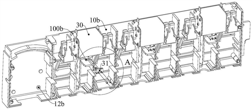
[0003] 1. Most of them have no fuse state detection. If you need to confirm the state of the fuse, you need to go to the site to measure and check, which is time-consuming and laborious.
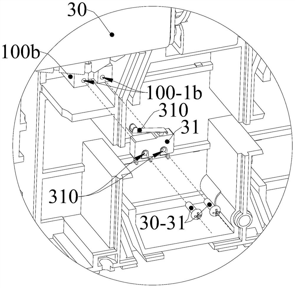
[0004] 2. In the existing load break switch with fuse state detection, the microswitches are also arranged on the fuse. When the user replaces the fuse, he needs to take off the microswitch first, and then pull out the fuse. After replacing the fuse Then install the micro switch, the operation is more complicated, and the power must be cut off before removing the micro switch, if the user replaces the fuse without power off, there will be safety hazards
[0005] 3. Most of the existing load break switches have no interphase partitions between the terminals. If the customer uses a large terminal or is applied in a high-voltage scene (especially AC1000V or DC1500V), the distance between the terminals will be too large. Insufficient clearances or creepage distances at close or high voltages, risk of phase-to-phase short-circuits
[0006] 4. The opening and closing speed of the existing load break switch depends on the speed of human operation, which affects the opening speed of the contact, which is not conducive to the rapid extinguishment of the arc

Method used


Image

  • Energy storage operating mechanism of load circuit breaker and load circuit breaker
  • Energy storage operating mechanism of load circuit breaker and load circuit breaker
  • Energy storage operating mechanism of load circuit breaker and load circuit breaker

Examples


Embodiment Construction

[0051] The following is attached Figure 1-24 The given examples further illustrate the specific implementation of the load break switch of the present invention. The load break switch of the present invention is not limited to the description of the following embodiments.

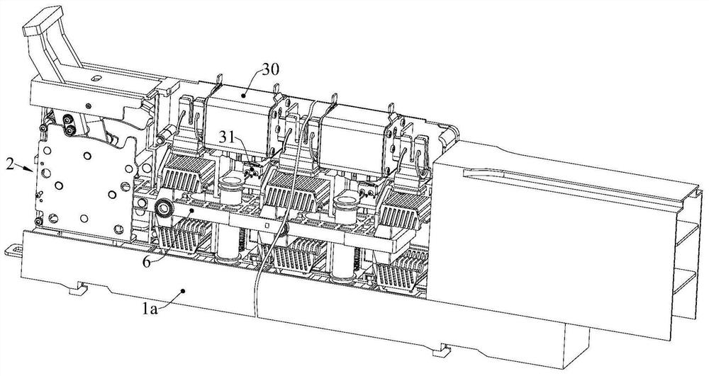
[0052] Such as figure 1 and 6 As shown, the load break switch of the present invention includes a switch housing 1, at least one disconnection pole circuit arranged in the switch housing 1, and an energy storage operating mechanism 2 respectively arranged at one end of the switch housing 1; the disconnection pole circuit includes a series The contact system and the fuse 30 are connected. The contact system includes a moving contact mechanism and a static contact group used in conjunction with the moving contact mechanism. The moving contact group on 6, the energy storage operating mechanism 2 drives the contact support 6 to drive the moving contact group and the static contact group to close / disconnect,...


PUM


Abstract

The invention relates to the field of low-voltage electric appliances, in particular to an energy storage operating mechanism of a load circuit breaker, which comprises a mechanism bracket, a handle assembly, an energy storage spring, a transmission connecting rod, a linkage rod and a first driving shaft, one end of the handle assembly is operated by a user and connected with one end of the energystorage spring, and the other end is arranged on the mechanism support in a pivoted mode. One end of the transmission connecting rod is pivotally arranged on the mechanism support, the other end of the transmission connecting rod is connected with the other end of the energy storage spring and one end of the linkage rod through a first driving shaft, and the other end of the linkage rod is in driving connection with a moving contact mechanism of the load circuit breaker. After the handle assembly is shifted to enable the energy storage spring to store energy, the energy storage spring releases energy to drive the transmission connecting rod to rotate through the first driving shaft, and drives the linkage rod to drive the moving contact mechanism to reciprocate at the same time; and according to the energy storage operating mechanism, the switching-on and switching-off speed of the load circuit breaker switch is increased. The invention further provides a load circuit breaker comprising the energy storage operating mechanism. The load circuit breaker is high in switching-on and switching-off speed.

Description

technical field [0001] The invention relates to the field of low-voltage electrical appliances, in particular to an energy storage operating mechanism of a load break switch and a load break switch including the energy storage operating mechanism. Background technique [0002] Existing load break switches, especially load break switches with bar-shaped switch housings, often have the following problems: [0003] 1. Most of them have no fuse state detection. If you need to confirm the state of the fuse, you need to go to the site to measure and check, which is time-consuming and laborious. [0004] 2. In the existing load break switch with fuse state detection, the microswitches are also arranged on the fuse. When the user replaces the fuse, he needs to take off the microswitch first, then pull out the fuse. After replacing the fuse Then install the micro switch, the operation is more complicated, and the power must be cut off before taking off the micro switch. If the user ...

Claims


Application Information

Patent Timeline
IPC IPC(8): H01H71/10
CPCH01H71/10
Inventor 刘亚南吴越韦尚靖徐永富吴昊
Owner ZHEJIANG CHINT ELECTRIC CO LTD
Learn More