Eureka AIR delivers breakthrough ideas for toughest innovation challenges, trusted by R&D personnel around the world.

Explosion-proof structure of medium-voltage power distribution cabinet door plate

An explosion-proof structure, power distribution cabinet technology, applied in substation/distribution device housing, substation/switchgear cooling/ventilation, electrical components, etc. Objects around the power distribution cabinet and pedestrian injuries, etc., to achieve the effect of improving explosion-proof performance, strengthening stability, and reducing injuries

Active Publication Date: 2020-12-08
国网河南省电力公司温县供电公司
View PDF4 Cites 6 Cited by
  • Summary
  • Abstract
  • Description
  • Claims
  • Application Information

AI Technical Summary

Problems solved by technology

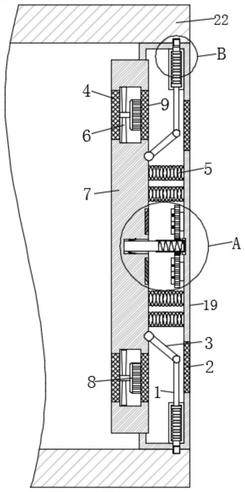
[0005] The purpose of the present invention is to solve the problem in the prior art that "existing power distribution cabinet door panels are rarely equipped with explosion-proof structures during use. Once an explosion occurs inside the power distribution cabinet, it is easy to cause damage to objects and pedestrians around the power distribution cabinet." damage, and the heat dissipation of the existing power distribution cabinet is not good enough", so an explosion-proof structure for the door panel of the medium voltage power distribution cabinet is proposed

Method used


Image

  • Explosion-proof structure of medium-voltage power distribution cabinet door plate
  • Explosion-proof structure of medium-voltage power distribution cabinet door plate
  • Explosion-proof structure of medium-voltage power distribution cabinet door plate

Examples


Embodiment Construction

[0021] The following will clearly and completely describe the technical solutions in the embodiments of the present invention with reference to the accompanying drawings in the embodiments of the present invention. Obviously, the described embodiments are only some, not all, embodiments of the present invention.

[0022] In describing the present invention, it should be understood that the terms "upper", "lower", "front", "rear", "left", "right", "top", "bottom", "inner", " The orientation or positional relationship indicated by "outside", etc. is based on the orientation or positional relationship shown in the drawings, and is only for the convenience of describing the present invention and simplifying the description, rather than indicating or implying that the referred device or element must have a specific orientation, so as to Specific orientation configurations and operations, therefore, are not to be construed as limitations on the invention.

[0023] refer to Figure ...


PUM


Abstract

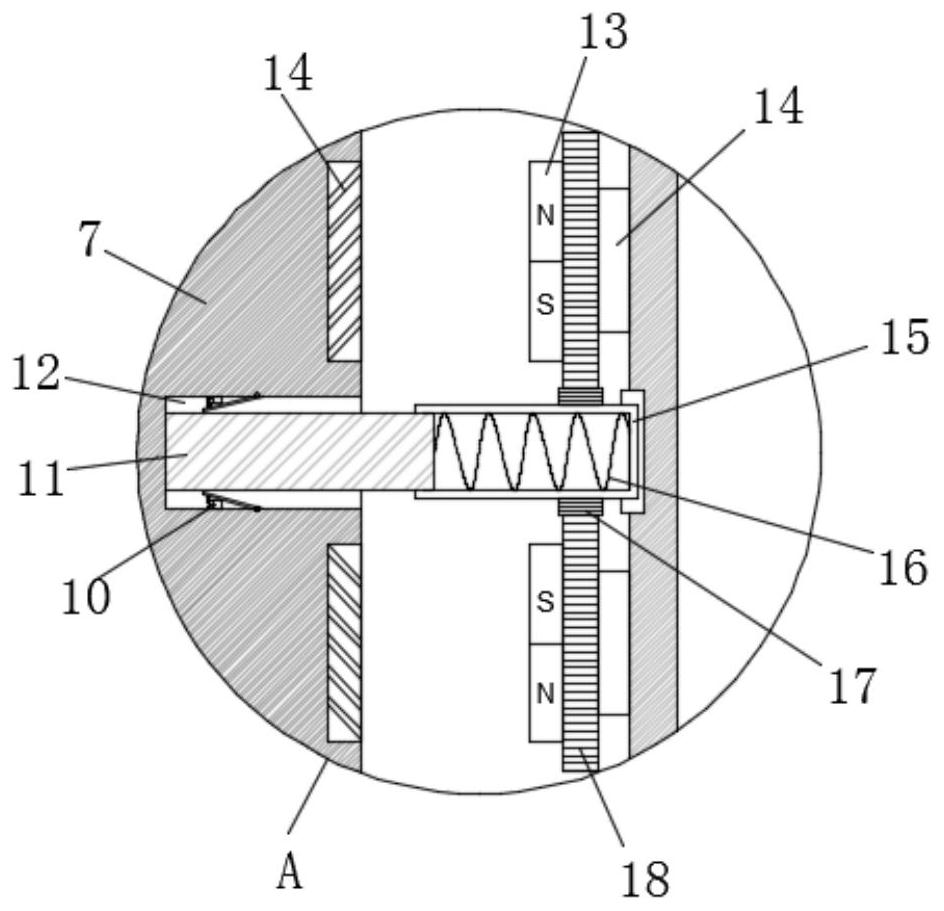
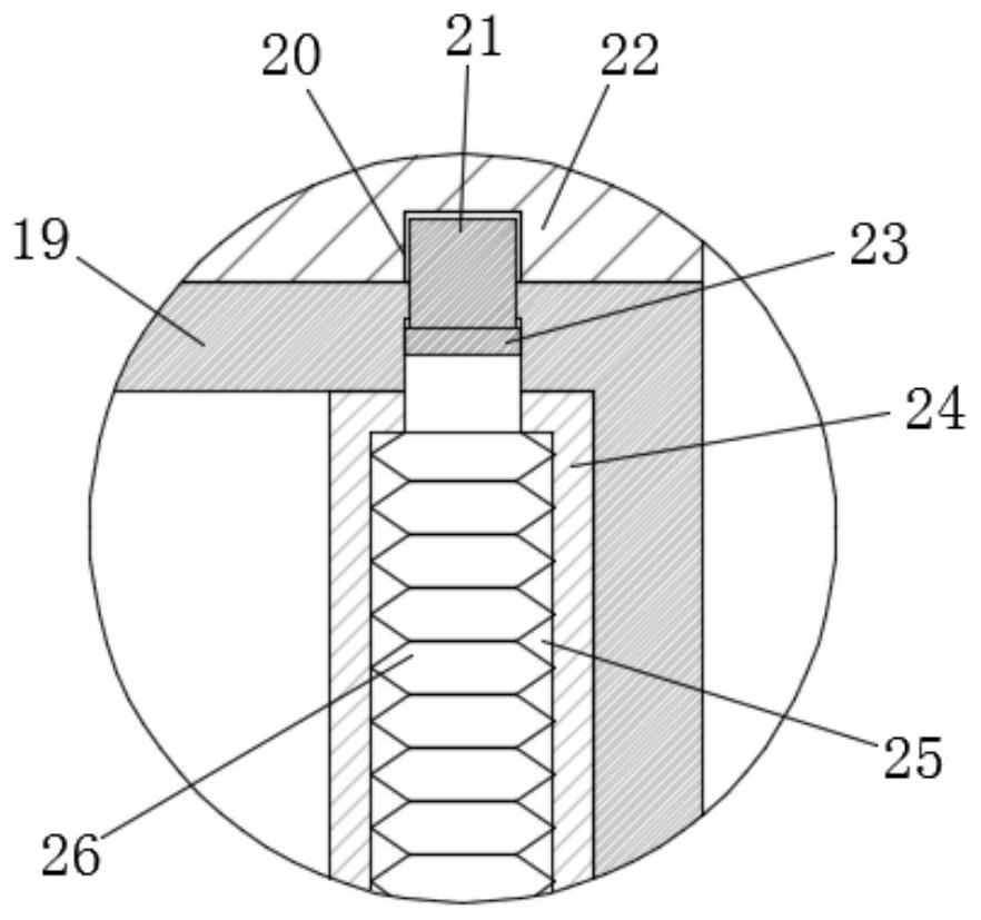
The invention discloses an explosion-proof structure of a medium-voltage power distribution cabinet door plate. The explosion-proof door plate comprises a cabinet body, a door plate body and an explosion-proof plate, the side wall of the door plate body is connected to the inner wall of the cabinet body through hinges, an explosion-proof cavity is formed in the door plate body, and the explosion-proof plate penetrates through the left side wall of the door plate body and is connected into the side wall of the door plate body in a sliding mode; a mounting groove is formed in the center of the right side wall of the explosion-proof plate, a touch switch is arranged on the side wall of the mounting groove, a threaded rod is fixedly mounted in the center of the mounting groove, the other end of the threaded rod is in threaded connection with a rotating cylinder, and the other end of the rotating cylinder is rotatably connected to the inner wall of the explosion-proof cavity; and a second spring is fixedly installed on the inner wall of the rotating cylinder, and the other end of the second spring abuts against the end, away from the explosion-proof plate, of the threaded rod. Accordingto the invention, impact force generated by explosion is prevented from rushing through the door plate body and hurting pedestrians around the cabinet body.

Description

technical field [0001] The invention relates to the technical field of a door panel of a power distribution cabinet, in particular to an explosion-proof structure of a door panel of a medium-voltage power distribution cabinet. Background technique [0002] The power distribution cabinet (box) is divided into power distribution cabinet (box), lighting distribution cabinet (box), metering cabinet (box), and is the final equipment of the power distribution system. The power distribution cabinet is a general term for the motor control center. The power distribution cabinet is used in the occasions where the load is relatively scattered and there are few circuits; the motor control center is used in the occasions where the load is concentrated and there are many circuits. They distribute the electric energy of a certain circuit of the upper-level power distribution equipment to the nearest load. This level of equipment shall provide protection, monitoring and control of the loa...

Claims


Application Information

Patent Timeline
Patent Type & Authority Applications(China)
IPC IPC(8): H02B1/30H02B1/56
CPCH02B1/30H02B1/565
Inventor 白俊峰陈向阳崔占齐王邦中林超褚贤勇郭卫旗杨太杰赵光辉杨沙沙李艳君
Owner 国网河南省电力公司温县供电公司
Why Eureka
Eureka Blog
Learn More