
Agricultural irrigation remote control water supply detection device based on Internet of Things

An agricultural irrigation and remote control technology, applied in measuring devices, watering devices, agriculture, etc., can solve the problems of time-consuming and labor-intensive management, the inability to detect water flow conditions in real time, and the inability to perform agricultural irrigation operations in a timely manner, achieving high accuracy , high work efficiency

Inactive Publication Date: 2020-12-11
SUZHOU RUIQI ELECTRONICS
View PDF17 Cites 0 Cited by
  • Summary
  • Abstract
  • Description
  • Claims
  • Application Information

AI Technical Summary

Problems solved by technology

[0002] Agricultural irrigation has always been in the stage of manual management. This management method is time-consuming and laborious, and obviously cannot meet the requirements of the large-scale production model.
In addition, due to the complex environmental conditions such as terrain, weather, and traffic, farmers cannot carry out agricultural irrigation operations in time. Although a large number of personnel are equipped to patrol wells during irrigation operations, they cannot quantitatively understand the irrigation situation and irrigation conditions in a timely manner. The operation of the equipment
[0003] Chinese patent (notification number: CN 105028136 B, announcement date: 2018.05.11) discloses an agricultural irrigation system based on the Internet of Things, including no less than one measurement and control terminal and a host computer, and the measurement and control terminal is installed on the well pump. For the measurement and control of well pumps, the host computer remotely controls the measurement and control terminal through the host computer software. The measurement and control terminal includes air switches, smart meters, card control contactors, RTUs, remote control contactors and pump safety protection devices, air switch input terminals and power supply lines The output terminals of the air switch are connected to the smart meter and the remote control contactor respectively; when the irrigation system is in use, it can realize functions such as intelligent dispatching, but when using pipelines for transportation, it is impossible to detect the water flow inside each section of the water pipe in real time situation, and whether there is water leakage, which is not conducive to the smooth irrigation of large areas and long distances

Method used


Image

  • Agricultural irrigation remote control water supply detection device based on Internet of Things
  • Agricultural irrigation remote control water supply detection device based on Internet of Things
  • Agricultural irrigation remote control water supply detection device based on Internet of Things

Examples


Embodiment 1

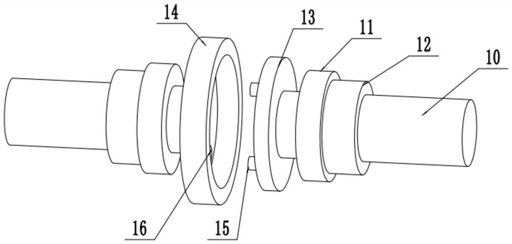
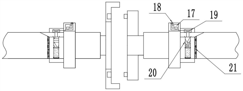
[0023] see Figure 1-4 , an agricultural irrigation remote control water supply detection device based on the Internet of Things, including a water pipe 10, fixed pipe sleeves 11 are fixedly installed at both ends of the water pipe 10, and the end of the water pipe 10 is fixed to a certain extent through the fixed pipe sleeve 11, The left and right ends of the water pipe 10 are respectively connected with a male valve 13 and a female valve 14. When connecting the two groups of water pipes 10, the male valve 13 and the female valve 14 are connected to each other, and the outer surface of the male valve 13 is fixedly installed. There are multiple groups of bayonet pins 15, and the inner surface of the female valve 14 is provided with a bayonet groove 16 plugged in with the bayonet pin 15. Through the connection between the bayonet pin 15 and the bayonet groove 16, it is convenient to further improve the communication between the male valve 13 and the female valve 14. of stabilit...

Embodiment 2

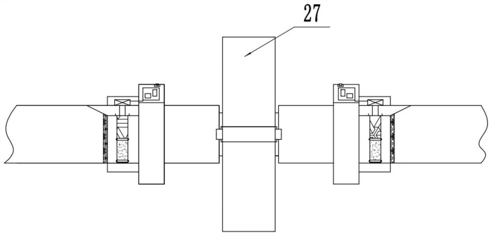
[0025] On the basis of Embodiment 1, a set of clamping sleeves 27 are detachably installed on the outer sides of the male valve 13 and the female valve 14. The clamping sleeves 27 are composed of two sets of upper and lower semicircles and rotate through the rotation shaft in the middle of the left side. Connection, the right middle part of the two groups of semicircles is fixedly connected with a horizontal extension plate 30 outward, and the upper and lower two groups of extension plates 30 are threaded with fastening bolts 31, and the fixed jacket 27 is tightly set and rotated by the fastening bolts 31. On the outer side when the male valve 13 and the female valve 14 are clamped together. The inner side of the first half of the fixed jacket 27 is fixedly installed with a rubber pad 28 for relieving pressure, and the inner side of the lower half is fixedly installed with a humidity detector 29 electrically connected to the main board 17. When the male valve 13 is connected to...


PUM


Abstract

The invention relates to the technical field of agricultural irrigation equipment, and discloses an agricultural irrigation remote control water supply detection device based on the Internet of Things. The device comprises a water pipe, and annular detection cavities arranged on the water pipe in a sleeving manner are fixedly mounted at the sides, away from the tail end of the water pipe, of fixedpipe sleeves. A set of electric elevator with the downward output end is fixedly mounted at the top of each annular detection cavity, the electric elevators are electrically connected with main boards, lifting rods movably stretching into the water pipe are connected to the bottoms of the electric elevators, and a set of folding pipe which is coaxial with the water pipe and has the same diameteras the water pipe is arranged at the position, the same as each annular detection cavaty, in the water pipe. Rotating shafts are arranged in the middles of the left side, the right side and the lowerside of each folding pipe correspondingly, the lower half portion of each folding pipe is made of rubber, and a set of water speed measuring instrument used for detecting water flow passing through the middle of the corresponding folding pipe and electrically connected with the corresponding main board is arranged in the middle of each lifting rod. The device has the advantages that whole-processwater delivery detection is achieved, accuracy is high, intelligent remote control is achieved, and working efficiency is high.

Description

technical field [0001] The invention relates to the technical field of agricultural irrigation equipment, in particular to an agricultural irrigation remote control water supply detection device based on the Internet of Things. Background technique [0002] Agricultural irrigation has always been in the stage of manual management. This management method is time-consuming and laborious, and obviously cannot meet the requirements of the large-scale production model. In addition, due to the complex environmental conditions such as terrain, weather, and traffic, farmers cannot carry out agricultural irrigation operations in time. Although a large number of personnel are equipped to patrol wells during irrigation operations, they cannot quantitatively understand the irrigation situation and irrigation conditions in a timely manner. The operation of the equipment. [0003] Chinese patent (notification number: CN 105028136 B, announcement date: 2018.05.11) discloses an agricultura...

Claims


Application Information

Patent Timeline
Patent Type & Authority Applications(China)
IPC IPC(8): A01G25/16G01D21/02H04B1/38H04L29/08
CPCA01G25/16G01D21/02H04B1/38H04L67/025
Inventor 不公告发明人
Owner SUZHOU RUIQI ELECTRONICS
Learn More