Tubular metal bending equipment with adjustable bending angle for metal forming

A bending angle and metal forming technology, applied in metal processing equipment, feeding devices, positioning devices, etc., can solve the problems of inconvenient movement, high labor intensity, inconvenient metal, etc., and achieve the advantages of easy cleaning, high efficiency and high automation level Effect

Inactive Publication Date: 2020-12-11
秦素容
View PDF6 Cites 0 Cited by
  • Summary
  • Abstract
  • Description
  • Claims
  • Application Information

AI Technical Summary

Problems solved by technology

The existing bending methods are mainly carried out manually, which has low efficiency, high labor intensity and poor safety
The body of the traditional bending equipment is large in size, poor in safety performance, and inconvenient to move. The body of the traditional bending equipment is fixed, which is not convenient for fixing the metal, and it is not convenient to adjust the length of the metal according to the actual situation. Adjustment, the traditional bending equipment body is not easy to bend metal, and it is not convenient to adjust the angle of metal bending. Pipe bending machine is a commonly used pipe processing equipment. There are many types of pipe bending machines For example, the pipe bending machine disclosed in the Chinese patent with the publication number of 110479813A includes a workbench, an active rotating part, a passive rotating part, a clamping device and a driving device for driving the rotating part of the active rotating part, and the active rotating part and the The passive rotating parts are respectively mounted on the workbench, the outer walls of the active rotating part and the passive rotating parts are provided with accommodating grooves on the same horizontal plane respectively, and the clamping device is installed on the A clamping hole is formed on the active rotating part and between the accommodating groove opposite to it. The output end of the driving device is connected to the active rotating part. The metal bending equipment mentioned above cannot be adjusted in time when it is formed. Bending angle, and the metal is prone to slipping during processing

Method used


Image

  • Tubular metal bending equipment with adjustable bending angle for metal forming
  • Tubular metal bending equipment with adjustable bending angle for metal forming
  • Tubular metal bending equipment with adjustable bending angle for metal forming

Examples


Embodiment 1

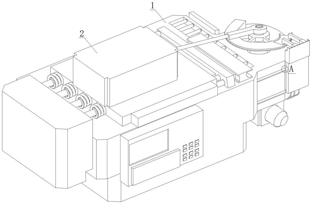
[0032] refer to figure 1 , figure 2 , Figure 4 and Image 6 , a tubular metal bending equipment with adjustable bending angle for metal forming, comprising a bearing mechanism 1 and a positioning and clamping mechanism 2, the upper end surface of the bearing mechanism 1 is equipped with the positioning and clamping mechanism 2, and the bearing mechanism 1 includes a main bearing platform 11. Arc-shaped workbench 12, turntable assembly 13 and bending assembly 14. A control platform 111 is installed on the outer wall of the main bearing platform 11, and an arc-shaped workbench 12 is welded on one side of the main bearing platform 11. The arc-shaped workbench The bottom end of 12 is provided with a rotating motor 121, the output end of the rotating motor 121 is connected to the turntable assembly 13, and the outer wall of the arc-shaped workbench 12 is movably connected to the bending assembly 14, and the upper end surface of the main bearing table 11 is fixed with a position...

Embodiment 2

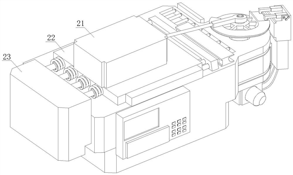
[0034] refer to image 3 and Image 6 The positioning and clamping mechanism 2 includes a mounting block 21, a base plate 22 and an air pump 23. The bottom end of the mounting block 21 is provided with a base plate 22. The output end of the air pump 23 is connected to the base plate 22 through a compression spring column 231, and the base plate 22 is far away from the air pump 23. One side is equipped with a positioning block 221; the side of the bottom plate 22 away from the air pump 23 is also equipped with a positioning clamp 222, and the side of the positioning clamp 222 close to the fixing groove 113 is processed with a positioning groove 2221, and the positioning groove 2221 is an arc-shaped groove body; the inner side of the positioning clamp 222 is provided with a chute 2222, and the outside of the positioning block 221 is provided with a slide block 2211 corresponding to the chute 2222, the positioning block 221 is flexibly connected to the positioning clamp 222 by th...

Embodiment 3

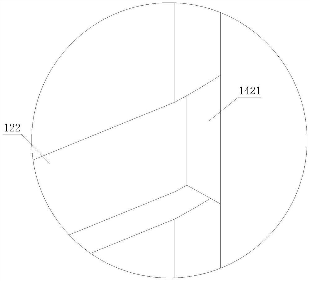
[0036] refer to Figure 5-8 , a tubular metal bending equipment with adjustable bending angle for metal forming. The turntable assembly 13 includes a turnrod 131, an arc-shaped turntable 132 and a fixing piece 133. The output end of the rotating motor 121 is connected to the turnrod 131, and the turnrobe 131 The upper end is fixed with an arc-shaped turntable 132, and the top of the rotating rod 131 is equipped with a fixing piece 133, and one end of the fixing piece 133 is connected to the mounting block 21 through an extension rod 1331; the bending assembly 14 includes a bending piece 141 and a servo motor 142, The upper end of the servo motor 142 is equipped with a bending piece 141, the top of the bending piece 141 is screwed with two sets of fixed sleeves 1411, and the inner cavity of the fixed sleeve 1411 is sleeved with an L-shaped telescopic fastener 14111, and the arc-shaped turntable One side of 132 is processed with a mounting groove 1321 near the upper end of the e...


PUM


Abstract

The invention discloses tubular metal bending equipment with an adjustable bending angle for metal forming. The equipment comprises a bearing mechanism and a locating and clamping mechanism, wherein the locating and clamping mechanism is mounted on the upper end face of the bearing mechanism. According to the equipment, a fixing groove is formed in the upper end of the side, close to an arc-shapedworkbench, of a main bearing table, and a plurality of rolling shafts are arranged in an inner cavity of the fixing groove; tubular metal can be firstly placed in the fixing groove before being bent,a bending assembly returns to the initial position, meanwhile, the inner side of a bending piece makes contact with the tubular metal, and the tubular metal is fixed; during bending, a servo motor and a rotating motor are started,the fixed tubular metal is driven to be bent by the arc movement of an arc-shaped electric sliding block in an arc-shaped sliding groove and the rotation of an arc-shaped rotating disc, the servo motor and the rotating motor can be stopped at any time in the moving process of the arc-shaped electric sliding block, and therefore the purpose of adjusting the bending angle is achieved; and compared with a traditional manual bending mode, the efficiency and the automation level are higher.

Description

technical field [0001] The invention relates to the technical field of bending devices, in particular to tubular metal bending equipment for metal forming with adjustable bending angles. Background technique [0002] Metal bending processing, the bending and forming of metal sheets are carried out on the bending machine, the workpiece to be formed is placed on the bending machine, the brake shoe is lifted by the lifting lever, the workpiece slides to the appropriate position, and then the brake is applied The shoe is lowered onto the workpiece to be formed, and the metal is bent and formed by applying force to the bending lever on the bending machine. The minimum bending radius is a function of the ductility and thickness of the formed metal. For aluminum sheets, the bending radius of the metal is greater than the thickness of the sheet. When bending, due to a certain amount of springback, the bending angle of the metal is slightly larger than the required angle, and the be...

Claims


Application Information

Patent Timeline
Patent Type & Authority Applications(China)
IPC IPC(8): B21D7/00B21D43/00
CPCB21D7/00B21D43/003
Inventor 秦素容
Owner 秦素容
Why Eureka
Try Eureka