Welding protection device and method used for thin-walled pipe

A protection device and thin-walled tube technology, applied in auxiliary devices, welding equipment, auxiliary welding equipment, etc., can solve the problems of limited welding space and low welding efficiency, improve welding efficiency, prevent welding deformation, and make up for welding space limited effect

Pending Publication Date: 2020-12-11
SHANGHAI ELECTRIC NUCLEAR POWER EQUIP CO LTD
View PDF0 Cites 3 Cited by
  • Summary
  • Abstract
  • Description
  • Claims
  • Application Information

AI Technical Summary

Problems solved by technology

The device and method aim to solve the problems of limited welding space and low welding efficiency of traditional thin-walled pipe welding equipment. The thin-walled pipe is tightened by fastening the sleeve and the fastening pin, and the first groove and the second groove are set. And evenly distributed through holes, so that the shielding gas is directly distributed into the second groove through the first groove, preventing welding deformation of thin-walled tubes, making up for the defect of limited welding space, and improving welding efficiency

Method used


Image

  • Welding protection device and method used for thin-walled pipe
  • Welding protection device and method used for thin-walled pipe
  • Welding protection device and method used for thin-walled pipe

Examples


Embodiment Construction

[0032] The present invention will be further described below through specific embodiments in conjunction with the accompanying drawings. These embodiments are only used to illustrate the present invention, and are not intended to limit the protection scope of the present invention.

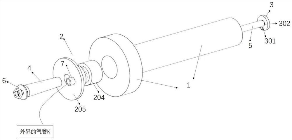
[0033] The present invention is a welding protection device for thin-walled pipe 1, such as figure 1 As shown, it includes fastening sleeve 2, top cover 3, fastening pin 4, screw rod 5, fixing piece 6 and intake pipe 7; in this embodiment, the material of the welding protection device is selected from carbon steel, low alloy steel or Any one or more of stainless steel.

[0034] Such as figure 1 As shown, the first end of the fastening sleeve 2 penetrates the first end of the thin-walled pipe 1 to be welded into the inside of the thin-walled pipe 1, and the second end clamps the second end of the thin-walled pipe 1; and the fastening sleeve The outer wall of the tube 2 fits the inner wall of the ...


PUM


Abstract

The invention discloses a welding protection device used for a thin-walled pipe. The welding protection device comprises a fastening casing pipe and a top cover. The first end of the fastening casingpipe penetrates into the thin-walled pipe, the second end of the fastening casing pipe clamps the second end of the thin-walled pipe, the outer wall of the fastening casing pipe cooperates with the inner wall of the thin-walled pipe, a first groove is formed in the inner wall of the fastening casing pipe in the axial direction of the fastening casing pipe, and the second end of the first groove communicates with an air pipe. A second groove is formed in the outer wall of the fastening casing pipe in the circumferential direction of the fastening casing pipe. Multiple through holes are evenly distributed in the bottom end of the second groove and communicate with the first groove and the second groove. The top cover is detachably connected with the first end of the fastening casing pipe, the outer diameter of the top cover is larger than the inner diameter of the fastening casing pipe, and the first groove is sealed. By means of the welding protection device, the problems that the welding space of the thin-walled pipe is limited and the welding efficiency is low are solved, the thin-walled pipe is expanded through the fastening casing pipe and a fastening pin, shielding gas is directly and evenly distributed into the second groove through the first groove, welding deformation of the thin-walled pipe is avoided, the defect that the welding space is limited is overcome, and the welding efficiency is improved.

Description

technical field [0001] The invention relates to the technical field of nuclear power thin-walled pipe welding, in particular to a welding protection device and method for thin-walled pipes. Background technique [0002] In the manufacture of the new reactor type vessel and reactor internals of the fourth generation nuclear power, the butt joint of thin-walled pipes and the butt welds between thin-walled pipes and flanges are involved. Due to the small size of the pipes, it is impossible to clean the root from the reverse side, and the bottom welding needs to be performed on one side. Welded double-sided molding. [0003] In the prior art, in order to ensure single-sided welding and double-sided forming of thin-walled pipes, the inner wall of the entire pipe is filled with inert gas (such as Ar), and the outer front is equipped with a U-shaped puller or a circular hoop on both sides of the weld. Anti-deformation fixed, play anti-deformation effect. [0004] However, when th...

Claims


Application Information

Patent Timeline
Patent Type & Authority Applications(China)
IPC IPC(8): B23K37/053B23K37/00B23K101/06
CPCB23K37/00B23K37/0531B23K2101/06
Inventor 张文杨张敏苏琦孙志远李双燕孟令奇罗庆
Owner SHANGHAI ELECTRIC NUCLEAR POWER EQUIP CO LTD
Why Eureka
Try Eureka