Coiling device for cable production

A coil and cable technology, applied in thin material handling, transportation and packaging, transportation of filamentous materials, etc., can solve the problems that the coil can not be easily off-line from the machine body, and the difficulty of recycling the finished coil, so as to achieve convenient Effects of placement and removal, weight reduction, and easy recycling

Inactive Publication Date: 2020-12-11
湖南新耒传导材料科技有限公司
View PDF1 Cites 4 Cited by
  • Summary
  • Abstract
  • Description
  • Claims
  • Application Information

AI Technical Summary

Problems solved by technology

The above-mentioned patents have the following disadvantages: the reel must be fixedly connected to the first rotating shaft to realize its own rotation, but the fixed connection leads to the fact that the reel cannot be easily disconnected from the body after the subsequent work of reeling is completed, and the recovery of the finished reel There is a certain difficulty and needs to be improved

Method used


Image

  • Coiling device for cable production
  • Coiling device for cable production
  • Coiling device for cable production

Examples


Embodiment 1

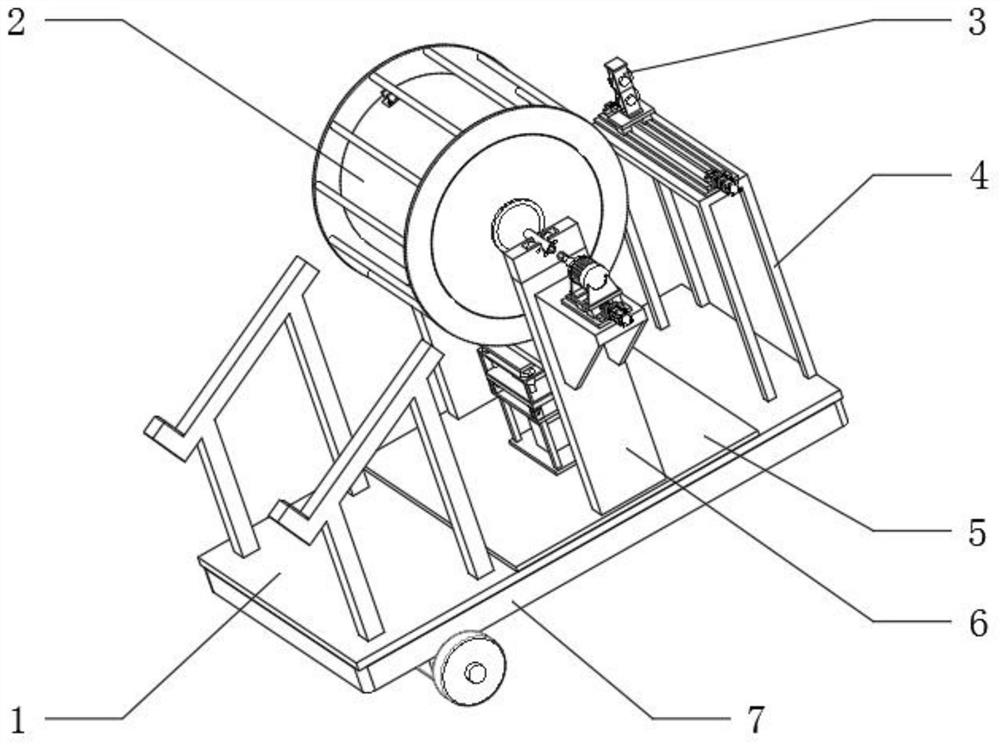
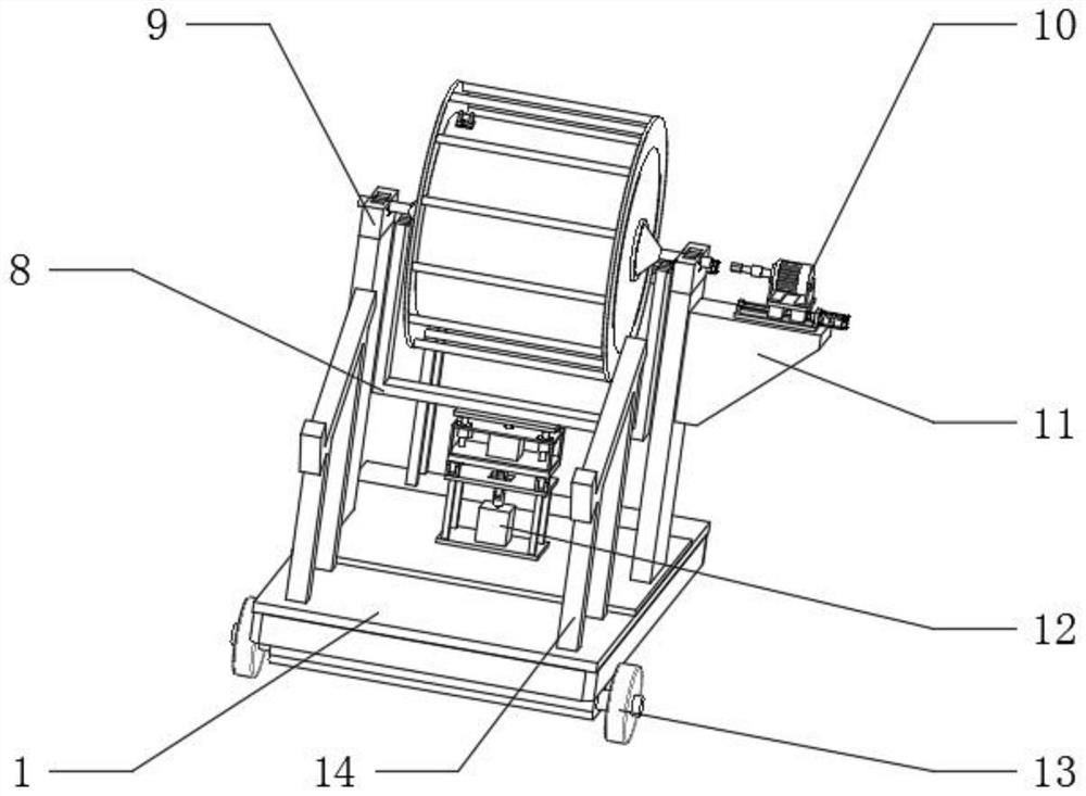
[0038] A coiling device for cable production, such as Figure 1-10 As shown, including the bottom plate 1, the top outer wall of the bottom plate 1 is fixedly connected with the supporting plate 5, the top outer wall of the supporting plate 5 is fixedly connected with the arm frame 6, the top outer wall of the arm frame 6 is fixedly connected with the support assembly 9, and the top outer wall of the support assembly 9 rotates The drum assembly 2 is connected, the outer wall of one side of the arm frame 6 is fixedly connected with a horizontal frame 11, the top outer wall of the horizontal frame 11 is fixedly connected with a rotary assembly 10, the top outer wall of the bottom plate 1 is fixedly connected with a stand 4, and the top outer wall of the stand 4 is fixedly connected with a The feeding assembly 3, the top outer wall of the bottom plate 1 is fixedly connected with the connecting assembly 12; the bottom outer wall of the bottom plate 1 is fixedly connected with a fra...

Embodiment 2

[0045] A coiling device for cable production, such as figure 1 As shown, in order to solve the problem of hunger and thirst; this embodiment makes the following improvements on the basis of Embodiment 1: the feed assembly 3 includes a second plate 44 and a vertical frame 42, and the outer wall of the bottom of the second plate 44 is fixedly connected to the vertical frame 4 Top outer wall, pasting plate 2 44 Top outer wall is fixedly connected with slide rail 2, slide rail 2 cooperates with slider 2, the top outer wall of slider 2 is fixedly connected with mobile plate 2, vertical frame 42 Bottom outer wall is fixedly connected to the top of mobile plate 2 The outer wall, the top outer wall of the pasting plate 2 44 is fixedly connected with the mounting frame 2, and the outer wall of the mounting frame 2 side is fixedly connected with the feeding motor, the output shaft of the feeding motor is connected with the screw rod 2 through a coupling, and the inner wall of the vertica...


PUM


Abstract

The invention discloses a coiling device for cable production, and relates to the technical field of cable processing equipment. The coiling device for cable production is used for achieving the purpose that a roller assembly can be independently taken out. The device specifically comprises a bottom plate. A supporting plate is fixedly connected to the outer wall of the top of the bottom plate, acantilever crane is fixedly connected to the outer wall of the top of the supporting plate, a supporting assembly is fixedly connected to the outer wall of the top of the cantilever crane, and a roller assembly is rotationally connected to the outer wall of the top of the supporting assembly. A stand frame is fixedly connected to the outer wall of the top of the bottom plate, a feeding assembly isfixedly connected to the top outer wall of the stand frame, and a connecting assembly is fixedly connected to the outer wall of the top of the bottom plate. According to the coiling device for cableproduction, because the supporting assembly is arranged, and a U-shaped groove is formed in the outer wall of the top of a fixed base, the roller assembly can conveniently go in and out of a device body vertically; and furthermore, because a first rotating wheel and a second rotating wheel are used in cooperation with trunnions, the roller assembly rotates on the outer wall of the top of the supporting assembly, and the roller assembly can be conveniently recycled after coiling work is completed.

Description

technical field [0001] The invention relates to the technical field of cable processing equipment, in particular to a coiling device for cable production. Background technique [0002] The existing cable processing equipment has poor effect on the cable winding process, mainly because the reel cannot be independent, that is, after the winding work is completed, there is no solution to the problem of how to realize the off-line of the reel, so it is necessary to design a A new coiling device for cable production. [0003] After retrieval, the Chinese patent application number is 201911276492.6, which discloses a wire and cable coiling machine, including a side frame, a coil sleeve, a first shaft, a first gear, a second gear, a first motor, a steering rod, The slide rail, the first sleeve, the third gear, the connecting rod, the fourth gear and the second motor; the side frame includes a first side wall; the first side wall is a vertical side wall; the first rotating shaft ro...

Claims


Application Information

Patent Timeline
Patent Type & Authority Applications(China)
IPC IPC(8): B65H54/553B65H54/72B65H54/70B65H54/28B65H67/04
CPCB65H54/2803B65H54/553B65H54/70B65H54/72B65H67/0411B65H2701/34
Inventor 赵峥孙爱国曾智俊曾小云汤小金
Owner 湖南新耒传导材料科技有限公司
Why Eureka
Try Eureka