Underground constant-pressure compressed air composite water pumping energy storage system and method based on waste mine

A compressed air, pumped water storage technology, applied in fuel systems, drainage, mining equipment, etc., can solve the problems of reduced system power generation efficiency, long recovery period, poor economy, etc., to maximize energy utilization and improve energy utilization. , the effect of reducing operating costs

Active Publication Date: 2020-12-11
XI AN JIAOTONG UNIV
View PDF6 Cites 11 Cited by
  • Summary
  • Abstract
  • Description
  • Claims
  • Application Information

AI Technical Summary

Problems solved by technology

Although pumped storage systems have many advantages over other energy storage systems, pumped storage systems still have unavoidable disadvantages
The pumped storage system requires upstream and downstream reservoirs to store water, and the upstream and downstream reservoirs of the pumped storage system need to be dammed, and the dam will cause damage to the ecological environment and affect the local ecosystem; in addition, the pumped storage system There are also disadvantages such as high investment cost, long payback period, and poor economy. The above characteristics make pumped storage systems unable to be widely used
Moreover, in the traditional compressed air energy storage technology (CAES), the volume of the gas storage container is fixed, and the pressure of the compressed air changes during the energy storage and energy release stages, which greatly reduces the power generation efficiency of the system.

Method used


Image

  • Underground constant-pressure compressed air composite water pumping energy storage system and method based on waste mine
  • Underground constant-pressure compressed air composite water pumping energy storage system and method based on waste mine
  • Underground constant-pressure compressed air composite water pumping energy storage system and method based on waste mine

Examples


Embodiment Construction

[0042] The present invention will be further described in detail below in conjunction with specific embodiments, which are explanations of the present invention rather than limitations.

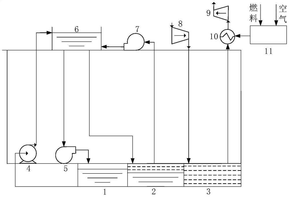
[0043] The present invention provides an underground constant-pressure compressed air composite pumping energy storage system based on an abandoned mine, including:

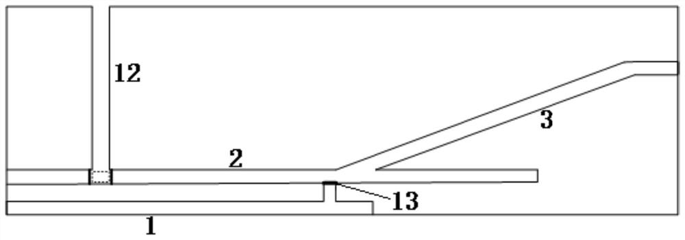
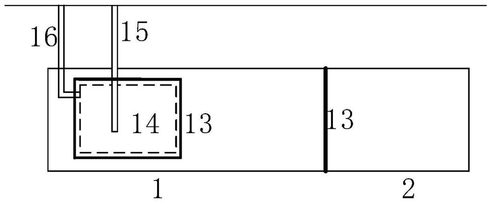
[0044] Underground return reservoir 1, horizontal roadway 2, underground mined-out area 3, above-ground reservoir 6 and central machine room; water delivery channel connects underground return reservoir 1 and above-ground reservoir 6, underground return reservoir 1 and horizontal roadway 2; gas transmission channel connects underground mining Empty zone 3 and horizontal roadway 2.

[0045] The first water turbine unit 5 is arranged between the underground return water reservoir 1 and the ground water reservoir 6, and the first water turbine unit 5 is used to generate electricity through the water delivery channel. The second hy...


PUM


Abstract

The invention discloses an underground constant-pressure compressed air composite water pumping energy storage system and method based on a waste mine. The system comprises the waste mine, an overground reservoir, an air compressor unit and an expansion unit. The waste mine comprises a horizontal roadway and an underground goaf, and the horizontal roadway communicates with the underground goaf. The overground reservoir communicates with the horizontal roadway through a pipeline. An air outlet of the air compressor unit is connected with an air inlet of the underground goaf through a pipeline,and an air outlet of the underground goaf communicates with an air inlet of the expansion unit arranged on the ground. The method comprises: an energy storage stage, wherein air is pressed into the underground goaf through the air compressor unit to form high-pressure air, the high-pressure air presses the water into the overground reservoir, the air pressure is kept constant, and constant-pressure energy storage is realized; and the energy release stage, wherein the air is exhausted outwards under the action of high pressure for power generation, the water in the overground reservoir supplements the volume of the air flowing out of the underground goaf, the air pressure constancy of the horizontal roadway and the underground goaf is achieved, and constant-pressure energy release power generation is achieved.

Description

technical field [0001] The invention relates to the field of energy storage, in particular to an underground constant-pressure compressed air composite pumping energy storage system and method based on an abandoned mine. Background technique [0002] In recent years, with the rapid development of intermittent energy sources such as wind energy and solar energy, the accompanying problems of curtailment of wind and light, and the grid connection of intermittent energy have brought many problems to the control and safe operation of the existing power grid. It is necessary to meet the large-scale grid-connected demand of intermittent energy and ensure the safe operation of the grid; the peak-shaving capability of the grid determines the ability of the grid to accept intermittent energy. [0003] At present, the peak regulation of the power grid mainly relies on thermal power units, which has been unable to solve the problem of grid connection of intermittent energy sources. The ...

Claims


Application Information

Patent Timeline
Patent Type & Authority Applications(China)
IPC IPC(8): F03B13/06F03B13/00F04B23/02F04B41/02E21F16/02E21F17/16E21F17/103F02B43/10F02B63/04F02G5/02F02C1/05
CPCF03B13/06F03B13/00F04B23/02F04B41/02E21F16/02E21F17/16E21F17/103F02B43/10F02B63/04F02G5/02F02C1/05F02B2043/103Y02E10/20Y02E60/16Y02T10/12Y02T10/30Y02P80/10
Inventor 王焕然陈昊李智搏张严杨珍帅李瑞雄
Owner XI AN JIAOTONG UNIV
Why Eureka
Try Eureka