Aero-engine fuel oil atomization characteristic simulation method and system

An aero-engine and simulation method technology, applied in design optimization/simulation, computer-aided design, special data processing applications, etc., can solve problems such as inability to capture gas-liquid two-phase, inability to deeply understand fuel atomization mechanism, and large amount of calculation question

Active Publication Date: 2020-12-11
西安科立仿真软件科技有限公司
View PDF5 Cites 7 Cited by
  • Summary
  • Abstract
  • Description
  • Claims
  • Application Information

AI Technical Summary

Problems solved by technology

[0008] The first interface tracking method is based on the Eulerian grid method, which obtains the actual interface position by solving the fluid volume fraction value in the grid and combining with the interface positioning technology. Although it can capture the details of the interface deformation and breaking process, but With the development of liquid film to liquid filament and then to liquid droplets and even smaller droplets, the interface of gas-liquid two-phase cannot be captured by too large grids, and grid self-adaptive technology needs to be used to continuously refine the grids, resulting in a huge amount of calculation. Usually, the calculation of the single-jet atomization process requires more than 200 hours of calculation by a high-performance computer with more than 5,000 cores. For the actual complex aero-engine fuel atomization device, it is extremely difficult to use this method for numerical simulation.
[0009] The second particle trajectory tracking method ignores the details of liquid film deformation and breakage, and directly adds the droplet distribution after fuel atomization into the flow field for calculation. Although it is suitable for tracking simulation of a large number of droplets, it can calculate evaporation and combustion processes. , but the mechanism of fuel atomization cannot be deeply understood, and the details of the fuel atomization process cannot be effectively obtained

Method used


Image

  • Aero-engine fuel oil atomization characteristic simulation method and system
  • Aero-engine fuel oil atomization characteristic simulation method and system
  • Aero-engine fuel oil atomization characteristic simulation method and system

Examples


Embodiment Construction

[0077] The object of the present invention is to provide a method and system for simulating the fuel atomization characteristics of an aero-engine, so as to reduce the calculation amount of the simulation of the aero-engine fuel atomization characteristics and realize the simulation of the details of the atomization process.

[0078] In order to make the above objects, features and advantages of the present invention more comprehensible, the invention will be further described in detail below in conjunction with the accompanying drawings and specific embodiments.

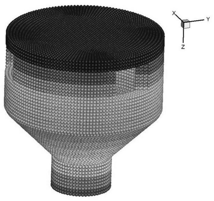
[0079] The technical scheme of the present invention is based on meshless particle simulation technology (smooth particle hydrodynamics method, SmoothedParticle Hydrodynamics, SPH) simulation aviation fuel atomization process, the design process of this technical method is as follows: (1) geometric model of aeroengine fuel atomization nozzle Establishment: According to the geometric configuration of the actual fuel a...


PUM


Abstract

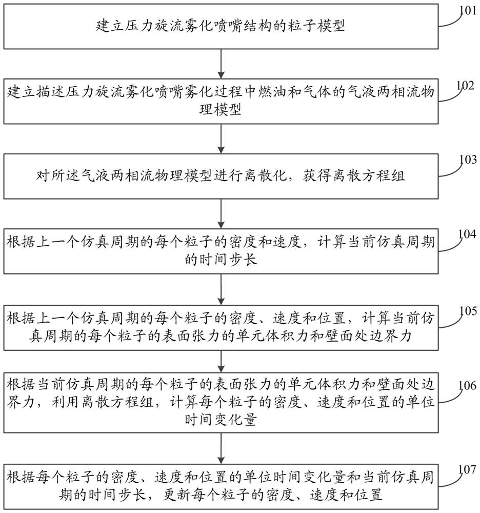
The invention discloses an aero-engine fuel oil atomization characteristic simulation method. The method comprises the steps of firstly, establishing a discrete equation set of a physical model for predicting aero-engine fuel oil atomization characteristics based on a smooth particle hydrodynamic method; then carrying out simulation based on the discrete equation set, and according to the densityand the speed of each particle in the previous simulation period, calculating the time step length of the current simulation period, the unit volume force of the surface tension of each particle and the boundary force of the wall surface; calculating the unit time variation of the density, the speed and the position of each particle by utilizing the discrete equation set; and updating the density,the speed and the position of each particle according to the unit time variation. The meshless particle simulation method for predicting the fuel oil atomization characteristics of the aero-engine has the advantages of being small in calculated amount, high in stability, adjustable in liquid attribute, traceable in liquid drop track and the like, and meanwhile has good practicability and expansibility.

Description

technical field [0001] The invention relates to the technical field of research on fuel atomization characteristics, in particular to a method and system for simulating the fuel atomization characteristics of an aero-engine. Background technique [0002] In order to meet the requirements of the new generation of military aircraft for tactical maneuverability, short-distance take-off, supersonic cruise and other excellent combat performance, as well as the requirements of civil aircraft for low cost, high cleanliness, and high reliability, future aero-engines must have high thrust-to-weight ratios and high-pressure ratios. , high temperature rise, and low pollution trends, which put forward more stringent standards for fuel combustion efficiency in the combustion chamber, stable operating range, outlet temperature distribution, fuel consumption rate, flame tube cooling, and pollutant emissions. As the initial stage of the combustion process, fuel atomization has a great influ...

Claims


Application Information

Patent Timeline
Patent Type & Authority Applications(China)
IPC IPC(8): G06F30/20G06F30/17G06F111/10G06F113/08
CPCG06F30/20G06F30/17G06F2111/10G06F2113/08
Inventor 陈福振严红
Owner 西安科立仿真软件科技有限公司
Why Eureka
Try Eureka