AMC-based low-profile circularly-polarized cross dipole antenna and communication equipment

A cross-dipole and circular polarization technology, which is applied in the direction of resonant antenna, antenna grounding device, and mid-position feed between antenna terminals, can solve the problems of signal fading and distortion, and achieve good circular polarization bandwidth and low height , the effect of increasing the gain value

Pending Publication Date: 2020-12-11
SOUTH CHINA UNIV OF TECH
View PDF0 Cites 5 Cited by
  • Summary
  • Abstract
  • Description
  • Claims
  • Application Information

AI Technical Summary

Problems solved by technology

However, in actual situations, the environment in which wireless communication systems are used is often complex and diverse, and the system is often subject to interference from the external environment. If linearly polarized antennas are used as the receiving and transmitting terminals of the communication system, sometimes multipath will occur. The signal fading and distortion caused by the effect, and the circularly polarized antenna can overcome this shortcoming

Method used


Image

  • AMC-based low-profile circularly-polarized cross dipole antenna and communication equipment
  • AMC-based low-profile circularly-polarized cross dipole antenna and communication equipment
  • AMC-based low-profile circularly-polarized cross dipole antenna and communication equipment

Examples


Embodiment 1

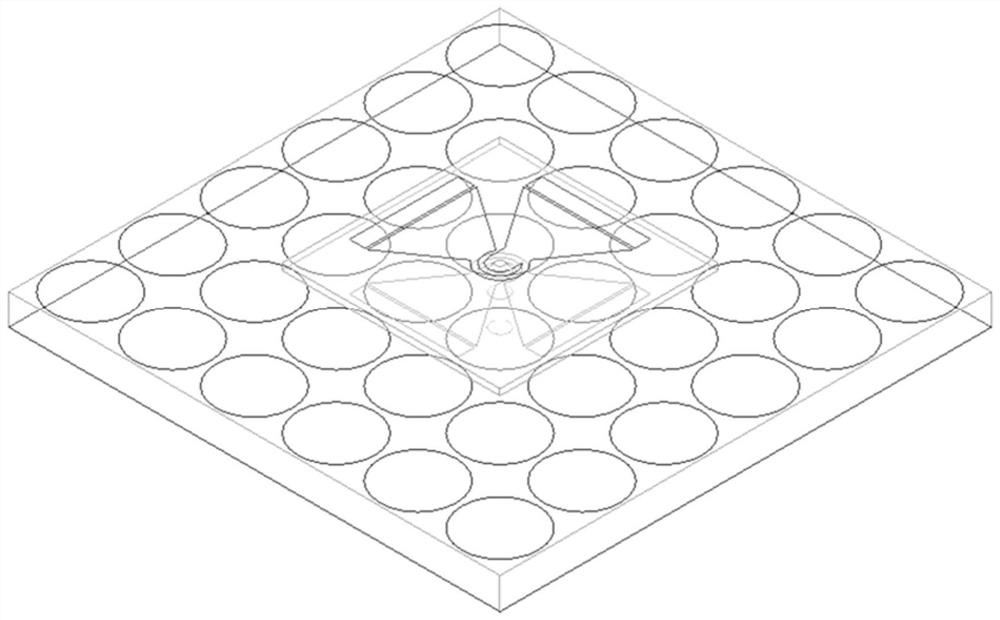
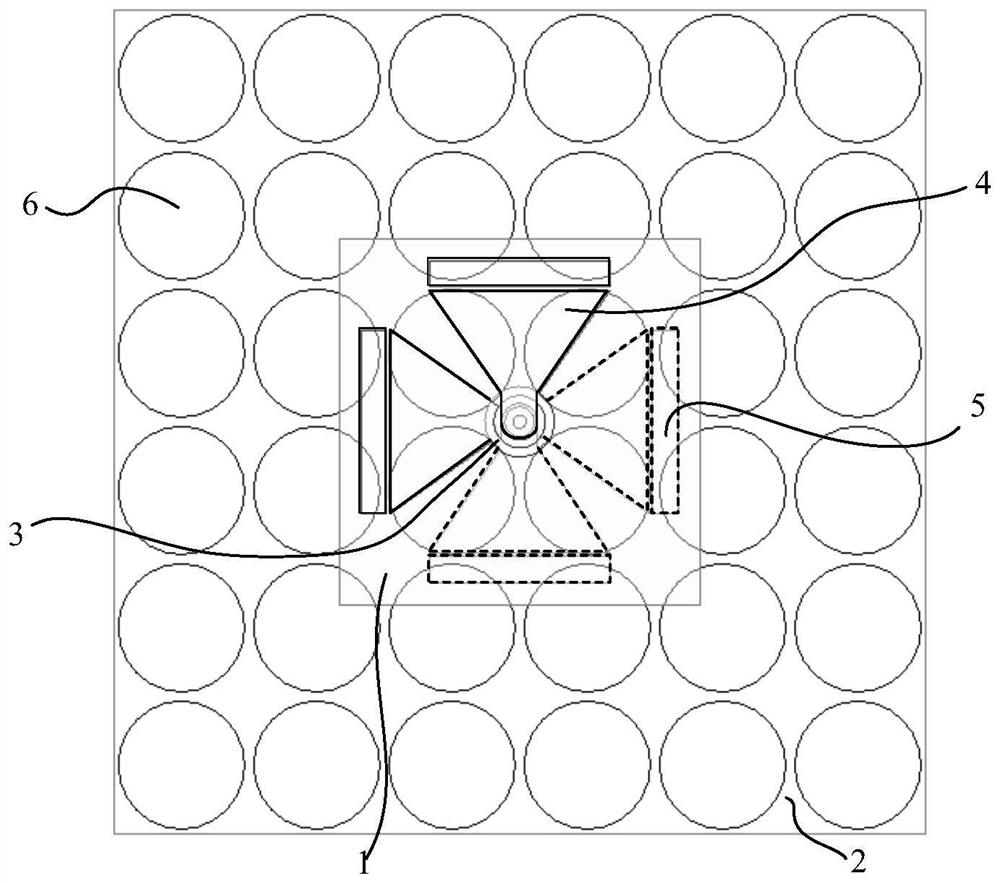
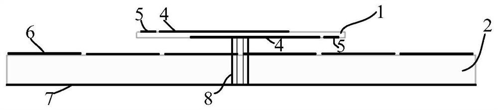
[0034] Such as Figure 1-Figure 3 As shown, an AMC-based low-profile circularly polarized crossed dipole antenna includes an upper dielectric substrate 1 , a lower dielectric substrate 2 , a main radiation unit, a parasitic unit 5 , an AMC metasurface 6 and a reflective floor 7 .

[0035] The upper dielectric substrate and the lower dielectric substrate are arranged in parallel and separated by a certain distance. Both the upper dielectric substrate and the lower dielectric substrate are square, and the center points are on the same straight line. In this embodiment, the size of the upper dielectric substrate 1 is 28mm×28mm and the size of the lower dielectric substrate 2 is 63mm×63mm, and the distance between them is 2.4mm.

[0036] The main radiation unit includes two pairs of dipoles 4 perpendicular to each other. The vertical intersection point is located at the center point of the upper dielectric substrate. The structural dimensions of the two pairs of dipoles are the sa...

Embodiment 2

[0050] A kind of communication equipment, comprises the circularly polarized crossed dipole antenna of low profile based on AMC, and this antenna comprises upper dielectric substrate, lower dielectric substrate, main radiation unit, parasitic unit, AMC metasurface and reflective floor;

[0051] The upper dielectric substrate and the lower dielectric substrate are arranged in parallel at a certain distance, the main radiation unit and the parasitic unit are arranged on the upper dielectric substrate, the upper surface of the lower dielectric substrate is provided with an AMC metasurface, and the lower surface is provided with a reflective floor;

[0052] The main radiating unit includes two pairs of dipoles, and the two pairs of dipoles are in a cross-shaped intersection structure, and the intersection point is located at the center point of the upper dielectric substrate.


PUM

PropertyMeasurementUnit
dielectric lossaaaaaaaaaa

Abstract

The invention discloses an AMC-based low-profile circularly-polarized cross dipole antenna and communication equipment. The AMC-based low-profile circularly-polarized cross dipole antenna comprises anupper dielectric substrate, a lower dielectric substrate, a main radiation unit, a parasitic unit, an AMC metasurface and a reflection floor, wherein the upper dielectric substrate and the lower dielectric substrate are arranged in parallel at a certain interval; the main radiation unit and the parasitic unit are arranged on the upper dielectric substrate; the upper surface of the lower dielectric substrate is provided with the AMC metasurface, and the lower surface of the lower dielectric substrate is provided with the reflection floor; and the main radiation unit comprises two pairs of dipoles, the two pairs of dipoles are of a cross-shaped cross structure, and a cross point is located at the center point of the upper dielectric substrate. The antenna has the characteristics of good circular polarization radiation performance, low profile and high gain, and can cover a part of C frequency bands of satellite communication.

Description

technical field [0001] The invention relates to the technical field of antennas, in particular to an AMC-based low-profile circularly polarized crossed dipole antenna and communication equipment. Background technique [0002] As the terminal of the wireless communication system, the main function of the antenna is to convert the electromagnetic wave radiated in the space into the current in the wire or convert the current in the wire into the electromagnetic wave radiated in space. It is an important part of the wireless communication system, and and The working performance of the communication system is closely related. In practice, the environment in which wireless communication systems are used is often complex and diverse, and the system is often subject to interference from the external environment. If linearly polarized antennas are used as the receiving and transmitting terminals of the communication system, sometimes multipath will occur. The signal fading and disto...

Claims


Application Information

Patent Timeline
Patent Type & Authority Applications(China)
IPC IPC(8): H01Q1/36H01Q1/38H01Q1/48H01Q9/16
CPCH01Q1/36H01Q1/38H01Q1/48H01Q9/16
Inventor 刘雄英翟志远范艺
Owner SOUTH CHINA UNIV OF TECH
Why Eureka
Try Eureka