A miniaturized multi-beam vortex beam generator

A generation device and multi-beam technology, applied in antenna grounding devices, antenna combinations with different interactions, and antenna arrays that are powered independently, can solve problems such as increased complexity, vortex beam influence, and large volume, and achieve design The effect of reducing difficulty, reducing feed loss, and expanding coverage

Active Publication Date: 2021-11-19
XIDIAN UNIV
View PDF0 Cites 0 Cited by
  • Summary
  • Abstract
  • Description
  • Claims
  • Application Information

AI Technical Summary

Problems solved by technology

Among them, the uniform circular array contains a large number of array elements, and the number of array elements increases with the increase of the vortex wave mode, resulting in an increase in the size and complexity of the array; the reflective array or the transmission array is the feed source There are strict requirements on the position relative to the front, and further feeds may affect the generated vortex beams
The vortex wave generating devices in the above two array forms are often bulky, which is not conducive to practical application
[0004] The existing single-antenna vortex wave generating device has a small volume and has the characteristics of miniaturization. However, due to the simple form of a single antenna, there are few parts that can be adjusted, so it can only generate simple vortex beams.
And because the antenna aperture of a single antenna is small, the divergence characteristics of vortex waves are more obvious, which further reduces its transmission effect, and the performance degradation is more serious when using it to generate high-order modal vortex waves
Therefore, it is difficult for the single-antenna vortex wave generating device to effectively control the vortex beam, reflecting its limitations in practical application.

Method used


Image

  • A miniaturized multi-beam vortex beam generator
  • A miniaturized multi-beam vortex beam generator
  • A miniaturized multi-beam vortex beam generator

Examples


Embodiment Construction

[0041] Embodiments of the present invention will be described in detail below in conjunction with examples, but those skilled in the art will understand that the following examples are only used to illustrate the present invention, and should not be considered as limiting the scope of the present invention.

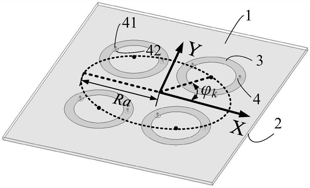
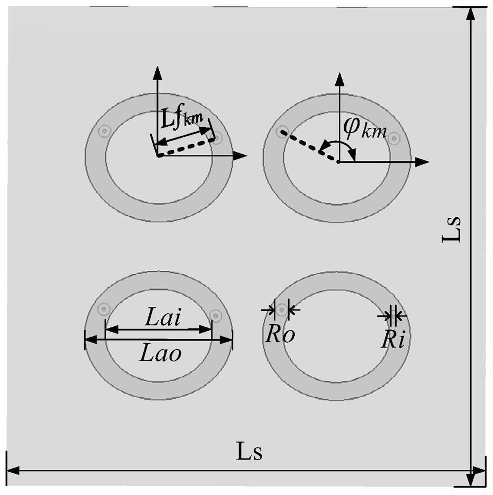
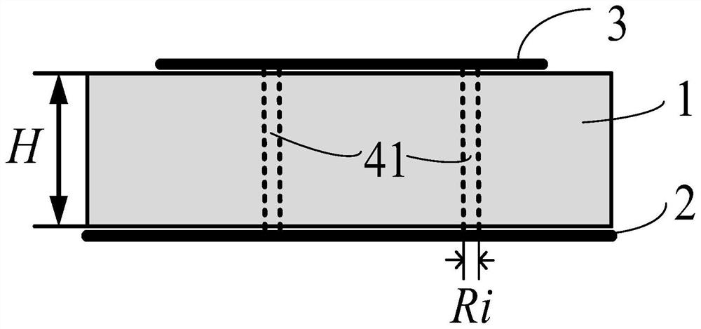
[0042] refer to Figure 1-Figure 3 , a kind of miniaturized multi-beam vortex beam generation device provided by the present invention, comprises: floor 2, dielectric substrate 1 and K microstrip antenna units, each microstrip antenna unit comprises elliptical annular microstrip antenna patch 3 and M A feeding port 4, each feeding port 4 is made up of a coaxial feeder 41 and an input port 42;

[0043]The lower surface of the dielectric substrate 1 is attached to the surface of the floor 2, and K elliptical annular microstrip antenna patches 3 are printed on the upper surface of the dielectric substrate 1, and the position centers of the K elliptical annular microstrip ant...


PUM

PropertyMeasurementUnit
lengthaaaaaaaaaa
heightaaaaaaaaaa
diameteraaaaaaaaaa

Abstract

The invention discloses a miniaturized multi-beam vortex beam generating device, which includes: a floor, a dielectric substrate and K microstrip antenna units, each microstrip antenna unit includes an elliptical annular microstrip antenna patch and M feed ports , each feed port is composed of a coaxial feed line and an input port; K elliptical loop microstrip antenna patches are printed on the dielectric substrate, and the center of its position is located on an outer ellipse; M pieces in each microstrip antenna unit The input ports are respectively etched on the floor, and the M coaxial feeders in each microstrip antenna unit are vertically embedded in the dielectric substrate. The present invention utilizes a small number of miniaturized antenna units for array design, and realizes multi-beam vortex waves; avoids the disadvantages of numerous array elements in existing array antennas and the problem of limited control capability of a single antenna beam, and makes the vortex beam generation device It has the characteristics of both miniaturization and wide beam coverage.

Description

technical field [0001] The invention relates to the technical field of antennas, in particular to a miniaturized multi-beam vortex beam generating device, which can be used in communication and radar systems. Background technique [0002] Radio technology has brought profound changes to all aspects of human life because it can realize the rapid transmission of information, and its related products have become an indispensable part of people's daily life. At the same time, the ever-increasing communication services make non-renewable spectrum resources increasingly scarce, and the communication rate tends to the limit of Shannon's theorem, posing challenges for further communication performance improvement. For this reason, radio-related technologies urgently need to make breakthroughs to solve the above problems, and electromagnetic waves as information carriers have also been extensively studied. Studies in recent years have shown that vortex electromagnetic waves (referre...

Claims


Application Information

Patent Timeline
Patent Type & Authority Patents(China)
IPC IPC(8): H01Q1/38H01Q1/48H01Q1/50H01Q1/52H01Q21/00H01Q21/06H01Q21/29
CPCH01Q1/38H01Q1/48H01Q1/50H01Q1/523H01Q21/0006H01Q21/065H01Q21/296
Inventor 李龙薛皓林屹峰徐鹏冯强
Owner XIDIAN UNIV
Why Eureka
Try Eureka