Rotor, asynchronous motor and compressor

A technology of rotor and rotor core, applied in asynchronous induction motors, electric components, electrical components, etc., can solve problems such as loss, increased material costs, and grid impact

Active Publication Date: 2020-12-11
GREE ELECTRIC APPLIANCES INC
View PDF5 Cites 0 Cited by
  • Summary
  • Abstract
  • Description
  • Claims
  • Application Information

AI Technical Summary

Problems solved by technology

Because the rotor current is the induced current, which causes the rotor speed to be 0 at the moment of starting the motor, the asynchronous motor presents a short-circuit impedance Zk to the power grid, and the current flowing through it is the starting current, and the starting current is generally 4-4% of the rated current 7 times, this will cause a great impact on the power grid, and at the same time, the starting current will cause loss in the line and inside the motor and cause heat
[0004] In order to reduce the starting current, the three-phase asynchronous motor usually uses a double squirrel cage slot or deep slot structure for the rotor, and uses the skin effect to reduce the starting current of the motor. cost, so a rotor that can reduce the starting current and reduce the use of materials has become an urgent need

Method used


Image

  • Rotor, asynchronous motor and compressor
  • Rotor, asynchronous motor and compressor
  • Rotor, asynchronous motor and compressor

Examples


Embodiment Construction

[0031] The motor starting current formula is as follows:

[0032]

[0033] In the formula, U 1 is the motor stator phase voltage; R 1 is the stator winding phase resistance at startup; R 2 ’ is the converted value of rotor resistance at startup; X 1σ is the stator leakage reactance at startup; X 2σ ’ is the converted value of the rotor leakage reactance at startup.

[0034] From the above formula, the inventor found that when the path of the motor rotor leakage magnetic circuit becomes larger, the leakage flux and leakage reactance will increase accordingly, and the starting current of the motor will decrease at this time. Based on this phenomenon, the inventor proposes the present invention.

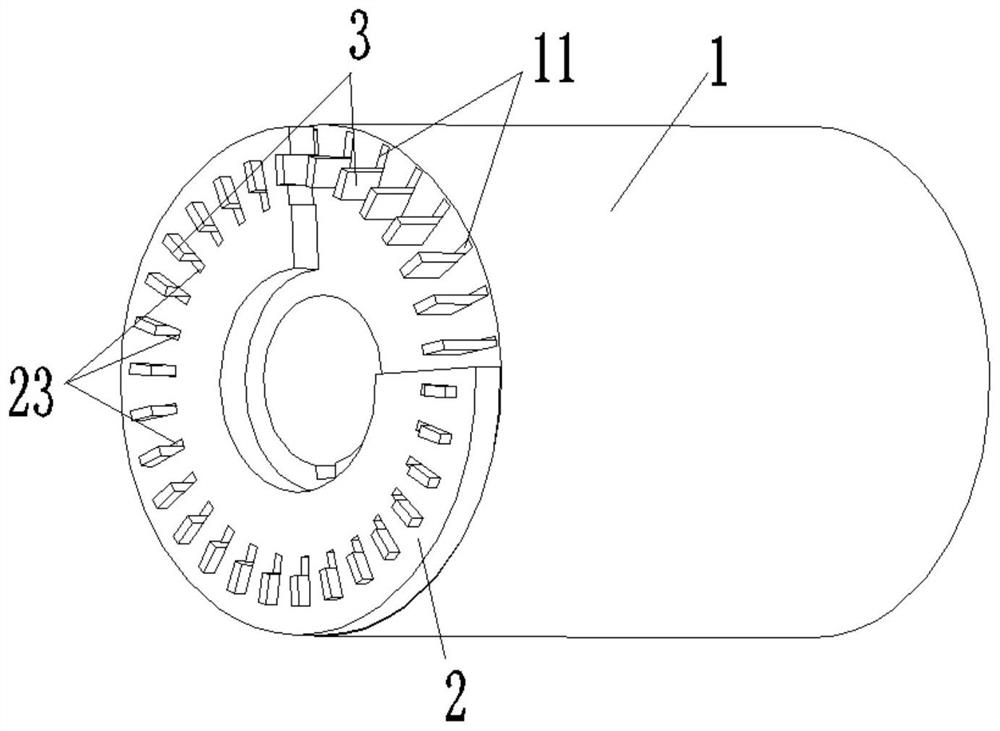
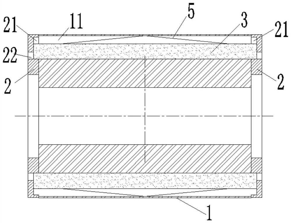
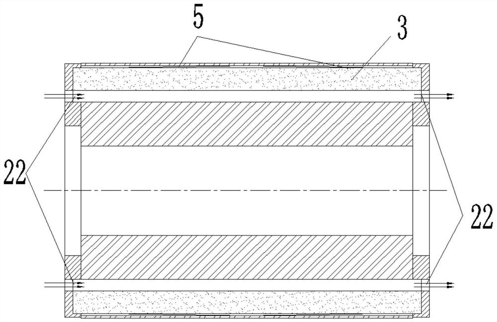
[0035] Specifically, see Figure 1 to Figure 9 As shown, according to an embodiment of the present invention, a rotor is provided, including a rotor core 1 fitted on a rotating shaft and end rings 2 at both ends of the rotor core 1 in the axial direction. There are a plurality ...


PUM


Abstract

The invention provides a rotor, an asynchronous motor and a compressor. The rotor comprises a rotor iron core sleeved on a rotating shaft and end rings located at two axial ends of the rotor iron core, the rotor iron core is provided with a plurality of guide bar grooves which are through along the axial direction of the rotor iron core, guide bars are arranged in the guide bar grooves, the guidebars are connected with the rotor iron core through the guide bar grooves, the guide bars and the end ring form a rotor mouse cage structure, when the rotor is static, the guide bars are located at afirst position close to the rotating shaft, when the rotor rotates, the guide bars are located at a second position away from the rotating shaft, and the guide bars can move between the first positionand the second position. According to the rotor, the asynchronous motor and the compressor, when the motor is started or the rotor is static, the guide bars are located at the first position, so thatthe magnetic flux leakage and the leakage reactance of the rotor iron core at the initial starting stage are improved, the starting current of the motor is further reduced, and the starting inertia of the motor can be reduced.

Description

technical field [0001] The invention belongs to the technical field of motor manufacturing, and in particular relates to a rotor, an asynchronous motor and a compressor. Background technique [0002] At present, in the motor industry, asynchronous motors are still widely used. Although the use of permanent magnet motors is also increasing, permanent magnet motors need to use permanent magnets, and the price of the motor is relatively expensive. Moreover, permanent magnets are easy to demagnetize, and the motor is safe and stable. It cannot be guaranteed. At the same time, the permanent magnet motor is generally used together with the controller, which increases the overall volume of the motor. The above shortcomings lead to the need to use a three-phase asynchronous motor as the drive in many occasions. [0003] The working principle of the three-phase asynchronous motor is: when the stator winding is fed with three-phase symmetrical current, the fundamental rotating magneto...

Claims


Application Information

Patent Timeline
IPC IPC(8): H02K3/12H02K17/16H02K1/32H02K3/50
CPCH02K1/32H02K3/12H02K3/50H02K17/165H02K2213/03
Inventor 赖涛卢素华沈静文刘思苑韦松韩允梅
Owner GREE ELECTRIC APPLIANCES INC
Why Eureka
Try Eureka