Load driving device
A technology of load driving and driving side, which can be used in measurement devices, circuit devices, control devices, etc., and can solve the problems of synchronous rectification circuits that cannot achieve accuracy.
- Summary
- Abstract
- Description
- Claims
- Application Information
AI Technical Summary
Problems solved by technology
Method used
Image


Examples
no. 1 Embodiment
[0025] figure 1 A circuit configuration diagram in this embodiment is shown.
[0026] The load driving device 101 includes a synchronous rectification circuit 104 including a high-side FET 102 and a low-side FET 103 . An inductive load 106 and a terminal capacitor 107 are connected to a synchronous rectification circuit output terminal 105 of the synchronous rectification circuit 104 . In the present embodiment, the synchronous rectification circuit 104 has a low-side configuration where the load 106 is connected to the power supply voltage VB. Therefore, the high-side FET 102 operates as a return-side switching element, and the low-side FET 103 operates as a driving-side switching element. The terminal capacitor 107 serves to protect the synchronous rectification circuit 104 from external surges.
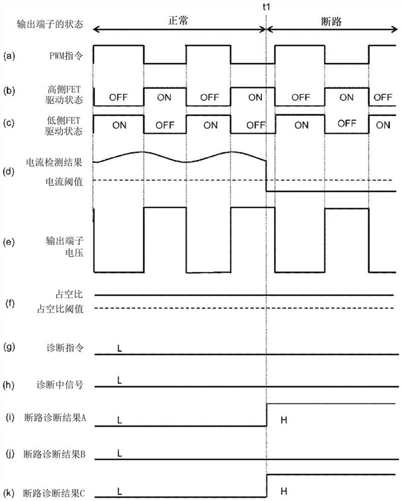
[0027] The drive control circuit 108 controls the respective gate voltages of the high-side FET 102 and the low-side FET 103 to turn ON / OFF according to the input PWM command.
...
no. 2 Embodiment
[0052] Figure 4 It is a circuit configuration diagram in the second embodiment. In this embodiment, the structure of the load 401 is different from that of the first embodiment. In addition, the same code|symbol is attached|subjected about the structure common to 1st Example, and description is abbreviate|omitted.
[0053] In this embodiment, the synchronous rectification circuit 104 has a high-side configuration in which the load 401 is connected to GND, the high-side FET 102 operates as a drive-side switching element, and the low-side FET 103 operates as a return-side switching element. Other configurations are the same as those of the first embodiment, and in the following description, descriptions will be made centering on parts different from the first embodiment.
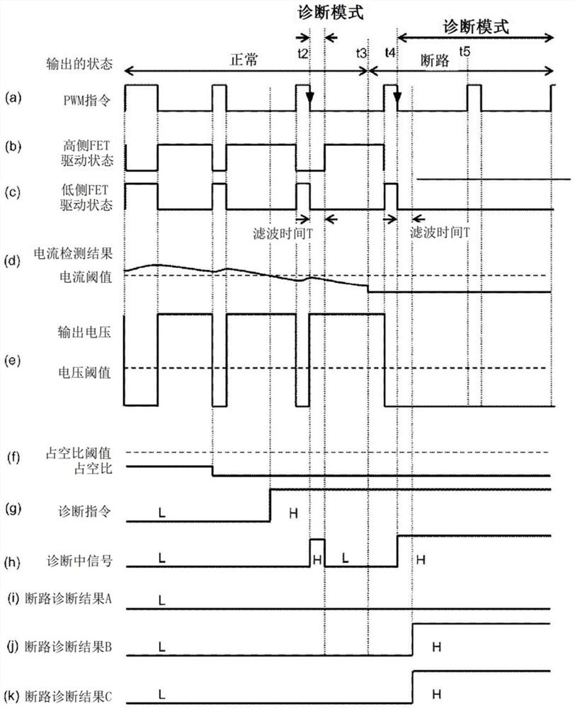
[0054] Figure 5 It is a timing chart showing an example of the operation of this embodiment. Since the synchronous rectification circuit 104 is a high-side configuration, in normal control Figure 5 Whe...
no. 3 Embodiment
[0060] Image 6 It is a circuit configuration diagram in the third embodiment. In this embodiment, the configuration of the input and output signals of the PWM command generation circuit 601 and the current detection circuit 109 is different from that of the first embodiment. In addition, the same code|symbol is attached|subjected about the structure common to 1st Example, and description is abbreviate|omitted.
[0061] The current detection circuit 109 receives a diagnosis signal from the drive control circuit 108 , and outputs the current detection result and an error signal indicating that the current detection result is incorrect to the PWM command generation circuit 601 .
[0062] The PWM command generating circuit 601 receives a current detection result, an error signal, and a current command value, and generates a PWM command so that the current flowing to the synchronous rectification circuit 104 becomes equal to the current command value. That is, when the error signa...
PUM
 Abstract
Description
Claims
Application Information
 - R&D
- Intellectual Property
- Life Sciences
- Materials
- Tech Scout
- Unparalleled Data Quality
- Higher Quality Content
- 60% Fewer Hallucinations
Browse by: Latest US Patents, China's latest patents, Technical Efficacy Thesaurus, Application Domain, Technology Topic, Popular Technical Reports.
© 2025 PatSnap. All rights reserved.Legal|Privacy policy|Modern Slavery Act Transparency Statement|Sitemap|About US| Contact US: help@patsnap.com