Processing technology of sintered porous bricks convenient to splice
A processing technology and technology of perforated bricks, applied in the field of perforated bricks, can solve the problems of error-prone, time-consuming and labor-intensive manual stacking, etc.
- Summary
- Abstract
- Description
- Claims
- Application Information
AI Technical Summary
Problems solved by technology
Method used
Image

Examples
Embodiment 1
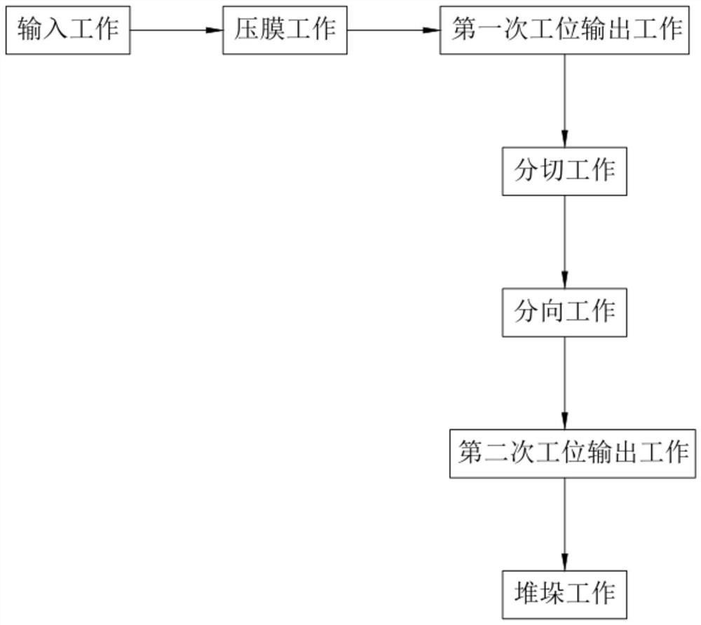
[0087] Such as figure 1 As shown, a sintered porous brick processing technology that is convenient for splicing includes:
[0088] Step 1, input work, the shifting member 122 sequentially transports the adobes 10 in the storage bin 121 backward along the length direction of the first transport platform 11;
[0089] Step 2, film pressing work, drive and start the horizontal push cylinder a211 of the lower mold assembly 21, the horizontal push cylinder a211 drives the resisting part 212 to move downward, and the pressing plate 215 presses against the top of the brick adobe and realizes the limit of the brick adobe, the resisting part 212 Continue to press down, the telescopic unit a2122 compresses, the punching shaft 2132 of the first mold part 213 moves down and punches the brick adobe until the lower end of the punching shaft 2132 moves to the position of the circular hole 113, the second mold part 214 The arc-pressing seat 2142 moves to the upper surface of the adobe 10, and...
Embodiment 2
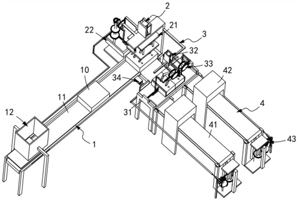
[0106] Such as figure 2 , Figure 20 As shown, a sintered porous brick processing production line that is convenient for splicing includes:
[0107] An automatic input mechanism 1, the automatic input mechanism 1 comprising a first transmission platform 11 and a dial assembly 12 arranged at the input end of the first transmission platform 11;
[0108] Forming mechanism 2, the forming mechanism 2 includes a lower mold assembly 21 arranged at the output end of the first transfer platform 11 and a mold assembly located on one side of the lower mold assembly 21 and perpendicular to the conveying direction of the material shifting assembly 12 Flat push assembly 22;
[0109] Cutting mechanism 3, described cutting mechanism 3 comprises the second conveying platform 31 that is vertically arranged with described first conveying platform 11 length direction, is arranged on the lower cutting assembly 32 that is arranged on described second conveying platform 31 top and is arranged on ...
Embodiment 3
[0158] Such as Figure 19 As shown, the parts that are the same as or corresponding to those in the second embodiment are marked with the corresponding reference numerals in the second embodiment. For the sake of simplicity, only the differences from the second embodiment will be described below. The difference between this embodiment three and embodiment two is:
[0159] further, such as Figure 19 As shown, the split assembly 33 includes a bidirectional rack 331 fixedly sleeved outside the connecting shaft 324, a first side shift assembly 332 located on one side of the cutout 311, and a side shift assembly 332 relative to the first side shift assembly. 332 is arranged on the second side shift assembly 333 on the other side of the cutout 311, and the lower ends of the first side shift assembly 332 and the second side shift assembly 333 are both slidably arranged on the second transfer platform 31 through a T-bar. On the T-groove 335, both sides of the bidirectional rack 331...
PUM
 Abstract
Description
Claims
Application Information
 - R&D Engineer
- R&D Manager
- IP Professional
- Industry Leading Data Capabilities
- Powerful AI technology
- Patent DNA Extraction
Browse by: Latest US Patents, China's latest patents, Technical Efficacy Thesaurus, Application Domain, Technology Topic.
© 2024 PatSnap. All rights reserved.Legal|Privacy policy|Modern Slavery Act Transparency Statement|Sitemap