
Textile drying control detection device

A drying control and detection device technology, applied in measuring devices, textile testing, drying, etc., can solve problems such as not being able to meet needs, and achieve the effects of simple structure, guaranteed drying efficiency, and convenient operation

Inactive Publication Date: 2020-12-15
台州椒江迈进针织有限公司
View PDF0 Cites 2 Cited by
  • Summary
  • Abstract
  • Description
  • Claims
  • Application Information

AI Technical Summary

Problems solved by technology

[0002] Textile refers to a multi-scale structure processing technology of fibers or fiber aggregates. After the general textiles are processed, they are printed. There are many printing methods, but they all need to be cleaned and dried after processing. Some special In order to ensure the completion of printing, textiles have certain requirements on temperature and humidity. The current drying equipment is relatively simple and can only perform simple drying operations, which cannot meet the needs.

Method used


Image

  • Textile drying control detection device
  • Textile drying control detection device
  • Textile drying control detection device

Examples


Embodiment Construction

[0020] All features disclosed in this specification, or steps in all methods or processes disclosed, can be combined in any way, except for mutually exclusive features and or steps.

[0021] Combine below Figure 1-6 The present invention is described in detail, and for convenience of description, the orientations mentioned below are now stipulated as follows: figure 1 The up, down, left, right, front and back directions of the projection relationship itself are the same.

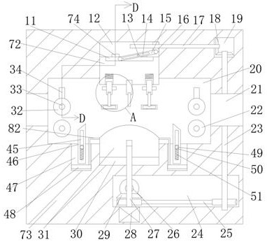
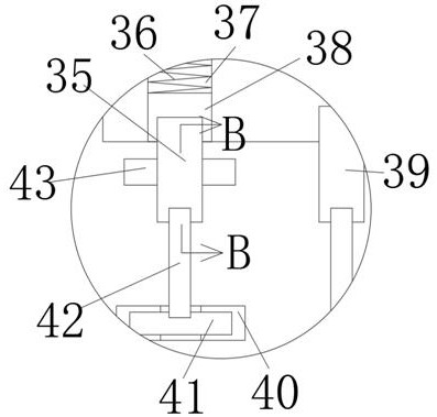
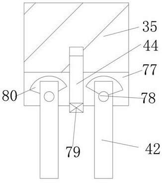
[0022] A textile drying control and detection device of the device of the present invention includes a box body 73, a working chamber 20 is arranged inside the box body 73, and a through hole 21 passing through the box body 73 is communicated with the left and right sides of the working chamber 20, The bottom wall of the working chamber 20 is provided with a lifting groove 30 with an upward opening, and an arc surface block 31 is slidably installed in the lifting groove 30, and the bottom wall of the worki...


PUM


Abstract

The invention discloses a textile drying control detection device. The textile drying control detection device comprises a box body, wherein a working cavity is formed in the box body; the left side and the right side of the working cavity are communicated with through holes penetrating through the box body; a lifting groove with an upward opening is formed in the bottom wall of the working cavity; a cambered surface block is mounted in the lifting groove in a sliding manner; reciprocating swing grooves with upward openings are symmetrically formed in the bottom wall of the working cavity andin the left side and the right side of the lifting groove; swing shafts extending front and back are rotationally mounted on the rear side walls of the reciprocating swing grooves; the swing shafts are connected with inclined surface swing rods extending into the working cavity; movable grooves penetrating front and back are formed in the inclined surface swing rods; the swing shafts are fixedly connected with fixed blocks in the inclined surface swing rods; and the fixed blocks are in sliding fit with the inner walls of the movable grooves. The device is simple in structure and convenient tooperate; a movable roller and the inclined surface swing rods move through movement between the cambered surface block and a supporting block, so that textiles are supported and fixed.

Description

technical field [0001] The invention relates to the technical field related to textile drying, in particular to a textile drying control and detection device. Background technique [0002] Textile refers to a multi-scale structure processing technology of fibers or fiber aggregates. After the general textiles are processed, they are printed. There are many printing methods, but they all need to be cleaned and dried after processing. Some special In order to ensure the completion of printing, textiles have certain requirements on temperature and humidity. The current drying equipment is relatively simple and can only perform simple drying operations, which cannot meet the needs. Contents of the invention [0003] Aiming at the deficiencies of the above-mentioned technologies, the present invention proposes a textile drying control and detection device, which can overcome the above-mentioned deficiencies. [0004] A textile drying control and detection device of the present...

Claims


Application Information

Patent Timeline
Patent Type & Authority Applications(China)
IPC IPC(8): F26B13/00F26B13/10F26B13/14F26B13/28F26B25/22G01N33/36
CPCF26B13/00F26B13/10F26B13/14F26B13/28F26B25/22G01N33/367
Inventor 鲁佳季
Owner 台州椒江迈进针织有限公司
Learn More