Optical fiber sensitive ring bidirectional synchronous measurement device and method based on Sagnac structure

A measuring device and two-way synchronization technology, which is applied in measuring devices, machine/structural component testing, optical instrument testing, etc., can solve problems such as the inability to guarantee the consistency of forward and reverse measurements, and eliminate the influence of false interference peaks , Simplify the structure of the device and eliminate the effect of influence

Active Publication Date: 2020-12-15
HARBIN ENG UNIV
View PDF12 Cites 0 Cited by
  • Summary
  • Abstract
  • Description
  • Claims
  • Application Information

AI Technical Summary

Problems solved by technology

Consistency of forward and reverse

Method used


Image

  • Optical fiber sensitive ring bidirectional synchronous measurement device and method based on Sagnac structure
  • Optical fiber sensitive ring bidirectional synchronous measurement device and method based on Sagnac structure
  • Optical fiber sensitive ring bidirectional synchronous measurement device and method based on Sagnac structure

Examples


Embodiment 1

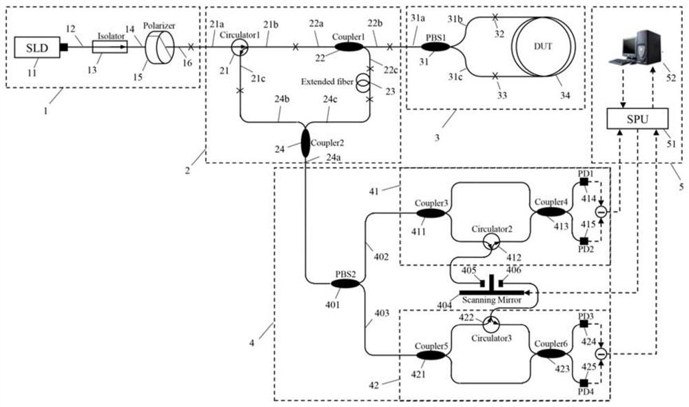
[0033] Embodiment one: a kind of optical fiber sensitive ring two-way synchronous measuring device based on Sagnac structure that the present invention proposes, such as figure 2 As shown, it includes a low-bias wide-spectrum light source module 1, a signal separation and extraction module 2, a Sagnac ring 3, a differential demodulation interferometer 4, a polarization crosstalk recording and processing module 5, and the two tail fibers of the optical fiber sensitive ring 34 to be tested are respectively connected to The two output ports 31b, 31c of the first optical fiber polarization beam splitter 31 are connected to form a Sagnac ring 3 together; the three ports 21a, 22b, 24a of the signal separation and extraction module 2 are respectively connected to the low-bias wide-spectrum light source module 1, The Sagnac ring 3 and the differential demodulation interferometer 4 are connected; specifically, it can be described as: the low-bias wide-spectrum light source module 1 inj...

Embodiment 2

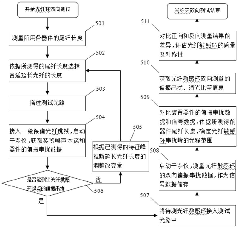
[0038] Embodiment two: a kind of optical fiber sensitive ring two-way synchronous measurement method based on Sagnac structure, introduce Sagnac structure, respectively inject the light of different polarization directions to the forward direction and reverse direction of optical fiber sensitive ring, adopt the demodulation interferometer of a differential scanning to two-way The measurement signal is demodulated to realize two-way synchronous measurement of the optical fiber sensitive ring; the specific process is as follows:

[0039] Step 1: Measure the length of the pigtail of the optical fiber device used; the specific device pigtails that need to be measured include: the pigtail of the optical fiber polarizer, the pigtails 21b and 21c of the first optical fiber circulator, and the tail of the first 1×2 fiber coupler fiber 22a, 22b, 22c, pigtail fibers 31a, 31b, 31c of the first optical fiber polarization beam splitter, pigtail fibers 24b, 24c of the second 1×2 fiber couple...


PUM


Abstract

The invention provides an optical fiber sensitive ring bidirectional synchronous measurement device and method based on a Sagnac structure. The device comprises a low-offset wide-spectrum light sourcemodule, a signal separation and extraction module, a Sagnac ring, a differential demodulation interferometer and a polarization crosstalk recording and processing module, and is characterized in thatthe Sagnac structure is introduced into a conventional test device; by employing light in different polarization directions, forward and reverse synchronous measurement is carried out on an optical fiber sensitive ring; and a differential scanning demodulation interferometer is adopted, and a bidirectional measurement result of any point in the optical fiber sensitive ring can be obtained at thesame time. The device is simple and novel in structure, is very small in difference between forward and reverse measurement, can effectively eliminate the impact from a pseudo interference peak in a test, improves the testing efficiency, and is of great significance to the reciprocity measurement and evaluation of the optical fiber sensitive ring and even optimization of an optical fiber sensitivering winding process.

Description

technical field [0001] The invention relates to a two-way synchronous measurement device and method for an optical fiber sensitive ring based on a Sagnac structure, and belongs to the technical field of optical device measurement. Background technique [0002] Fiber optic gyroscope is an inertial instrument in the field of navigation and guidance. It is based on the Sagnac effect and can realize the sensing and measurement of rotational angular velocity. The polarization-maintaining optical fiber ring is the core sensitive part of the fiber optic gyroscope system. It is made of a polarization-maintaining optical fiber of hundreds of meters to several kilometers in accordance with certain processes and rules. The purpose is to improve the sensing performance of the fiber optic gyroscope. From the sensing principle of the fiber optic gyroscope, it can be known that the fiber optic gyroscope can achieve precise navigation only when the forward and reverse optical signals along ...

Claims


Application Information

Patent Timeline
IPC IPC(8): G01M11/00
CPCG01M11/331G01M11/337
Inventor 杨军林蹉富朱云龙党凡阳张浩亮张翔苑勇贵苑立波
Owner HARBIN ENG UNIV
Why Eureka
Try Eureka