

Polarizing plate, manufacturing method thereof, and optical device
A technology for polarizers and transparent substrates, which is applied in the direction of instruments, optics, and polarizing components. It can solve problems such as poor heat resistance or light resistance, and concerns about long-term use, and achieve low reflectivity, improved mechanical strength, and high transmittance. Effect
- Summary
- Abstract
- Description
- Claims
- Application Information
AI Technical Summary
Problems solved by technology
Method used
Image

Examples
Embodiment 1~5 and comparative example 1
[0129] [Production of polarizer]
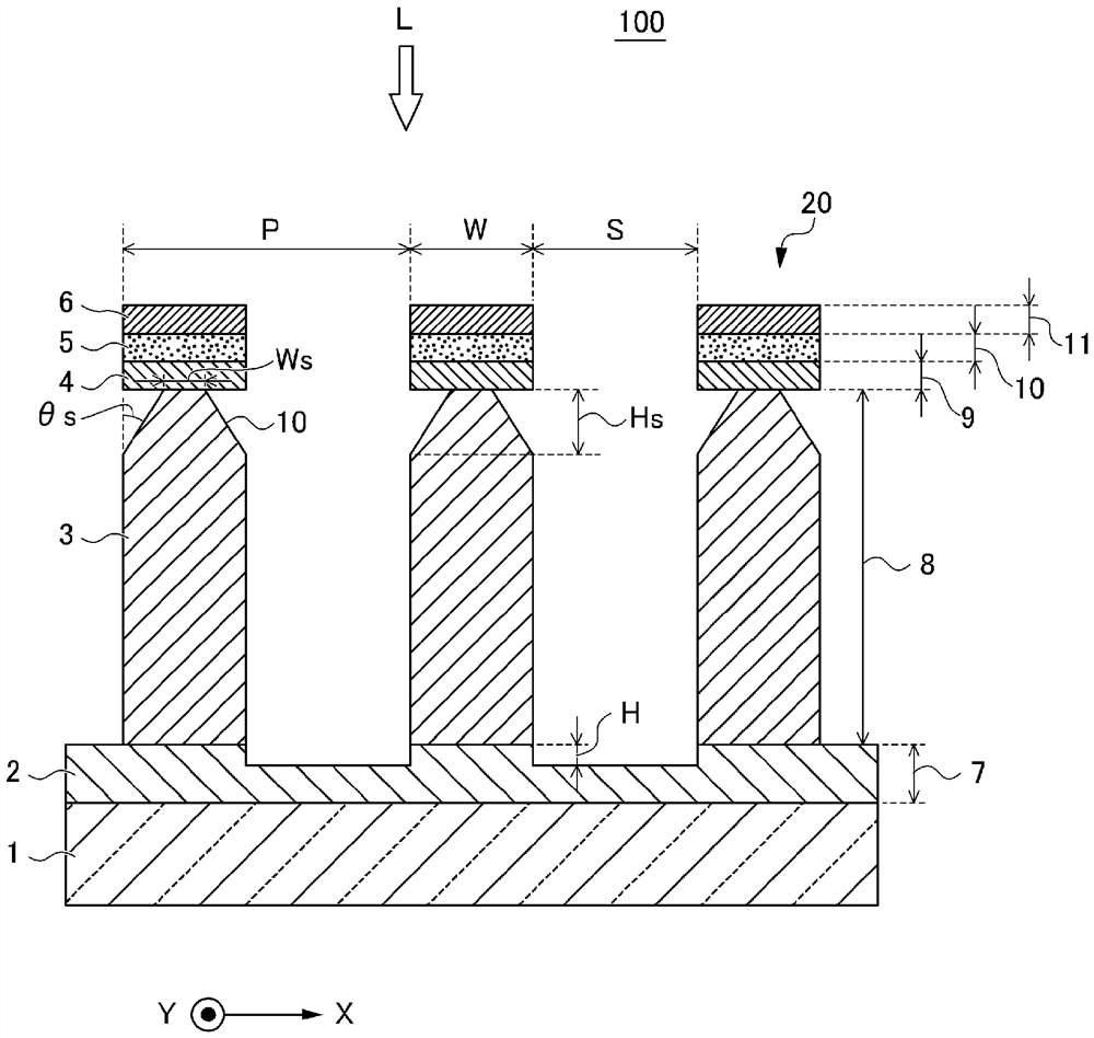
[0130] In Examples 1 to 5, as having figure 1 The polarizer 100 of the structure shown, and the step angle of the reflective layer 3 θ Polarizers with s of 87˚, 45˚, 21˚, 8˚, and 4˚ were used for simulation.
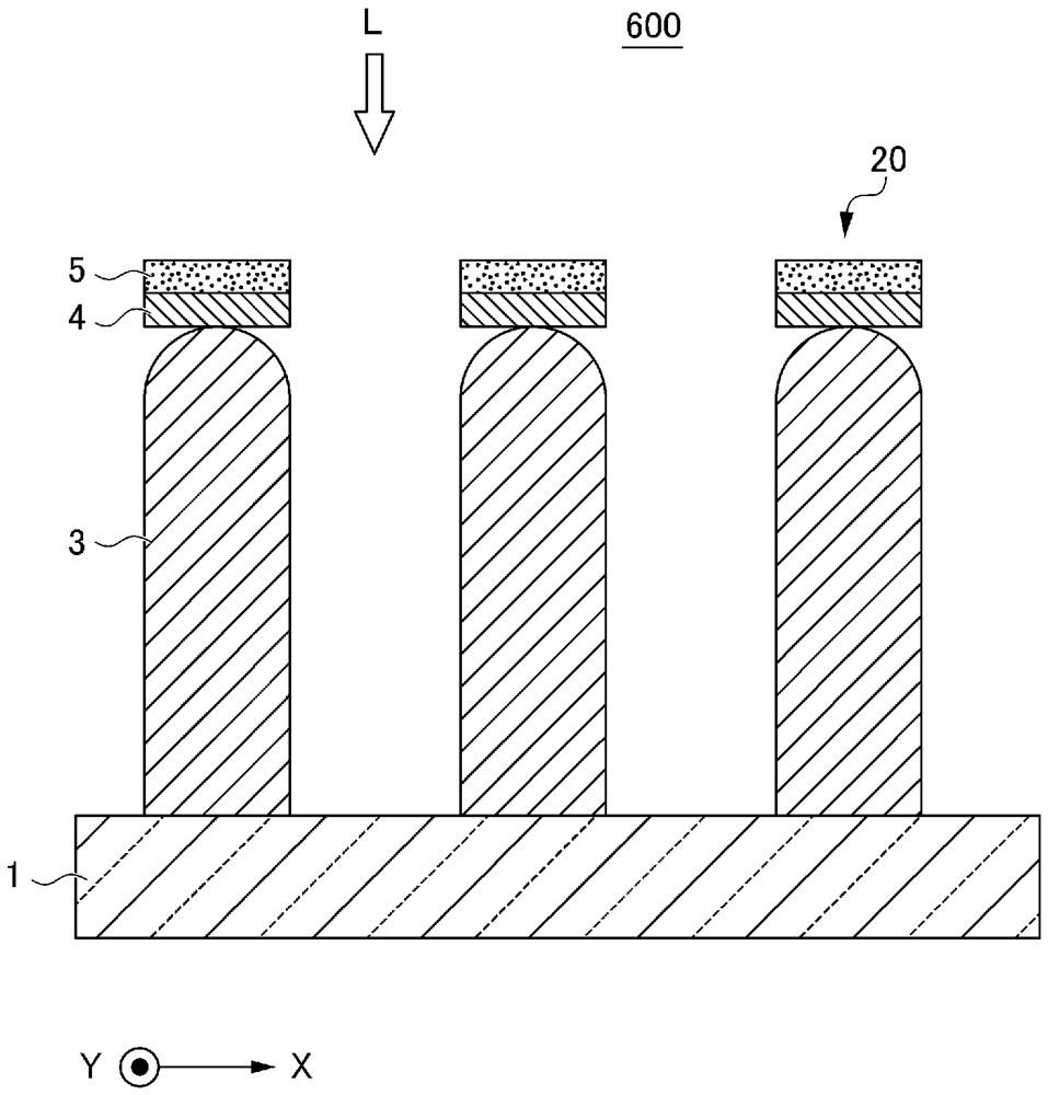
[0131] In addition, as Comparative Example 1, a polarizing plate 200 different from the polarizing plate 100 of Example 1 only in the structure of the absorbing layer 3 was fabricated and used for simulation. The polarizing plate 200 that became Comparative Example 1 was figure 2 In the shown structure, when viewed from the direction in which the lattice-shaped protrusions 20 extend (predetermined direction: Y-axis direction), that is, in a cross-sectional view perpendicular to the predetermined direction, the reflective layer 3 has a rectangular shape and does not have steps (steps). timing θ s=0°).
[0132] Step angle in polarizer 100 θ s is obtained by Equation 1 below.
[0133] [Formula 1]
[0134] θ s=arctan{Hs / (W﹣Ws)...
PUM
| Property | Measurement | Unit |
|---|---|---|
| wavelength | aaaaa | aaaaa |
| refractive index | aaaaa | aaaaa |
| refractive index | aaaaa | aaaaa |
Abstract
Description
Claims
Application Information