
Anti-deformation and efficient automatic material cleaning and taking-out device for long and thin steel plate

A technology for taking out devices and thin steel plates, which is applied in the field of metal materials, can solve problems such as increased working time, deformation of long and thin steel plates, and reduced product quality, and achieves the effects of reducing work intensity, preventing bending deformation, and improving work efficiency

Inactive Publication Date: 2020-12-18
XIANGSHAN XUWEN STEEL TECH CO LTD
View PDF12 Cites 0 Cited by
  • Summary
  • Abstract
  • Description
  • Claims
  • Application Information

AI Technical Summary

Problems solved by technology

[0002] The current long and thin steel plate blanking equipment usually needs to manually clean up the side material produced during the blanking process. In mass production, the work intensity of the workers is relatively high. On the other hand, after the blanking is completed, the blanking equipment The upper mold of the upper mold is usually raised upwards to facilitate the workers to take out the long and thin steel plates, but the large lifting of the upper mold increases the working time and reduces the work efficiency. It is easy to deform long and thin steel plates, thereby reducing the quality of the product

Method used


Image

  • Anti-deformation and efficient automatic material cleaning and taking-out device for long and thin steel plate
  • Anti-deformation and efficient automatic material cleaning and taking-out device for long and thin steel plate
  • Anti-deformation and efficient automatic material cleaning and taking-out device for long and thin steel plate

Examples


Embodiment Construction

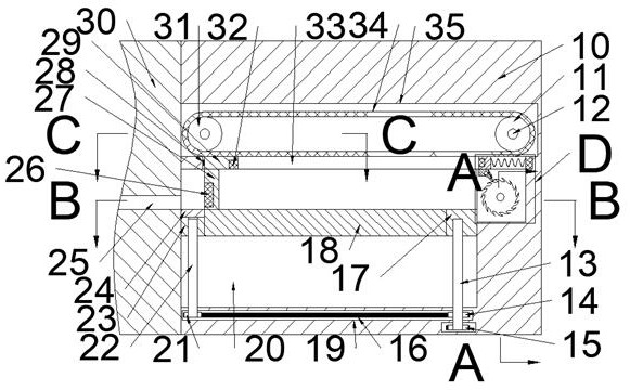
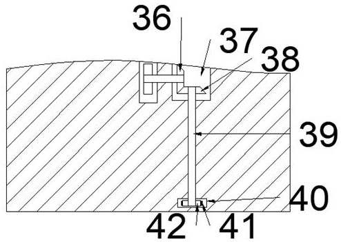
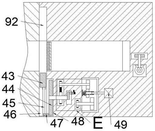
[0020] Combine below Figure 1-6 The present invention is described in detail, wherein, for the convenience of description, the orientations mentioned below are defined as follows: figure 1 The up, down, left, right, front and back directions of the projection relationship itself are the same.

[0021]A kind of anti-deformation and high-efficiency automatic cleaning and taking-out device for long and thin steel plates described in conjunction with accompanying drawings 1-6 includes a main box body 10, and a punching machine 30 is fixedly connected to the left end of the main box body 10. The cutting machine 30 is provided with a left and right punching chamber 25, and the main box 10 is provided with a take-out belt chamber 35, and the front side of the take-out belt chamber 35 is provided with a bevel tooth chamber 52 for taking out, and the take-out belt chamber The front side of 35 is provided with an upward belt chamber 77 which is located on the right side of the bevel t...


PUM


Abstract

The invention relates to the related field of metal materials, and discloses an anti-deformation and efficient automatic material cleaning and taking-out device for a long and thin steel plate. The anti-deformation and efficient automatic material cleaning and taking-out device comprises a main box body, wherein a blanking machine is fixedly connected to the left end face of the main box body, a left-right through blanking cavity is formed in the blanking machine, a taking-out belt cavity is formed in the main box body, and a conical tooth cavity for taking out is formed in the front side of the taking-out belt cavity; an upward belt cavity which is located at the right side of the taking-out conical tooth cavity and extends downwards is formed in the front side of the taking-out belt cavity, and a rotary disc protruding block and a connecting rod drive a push-out sliding block to slide back and forth in a reciprocating manner, so that blanking edge materials are automatically pushed into a waste cavity, and the working intensity of workers is reduced; a taking-out connecting block and a taking-out electromagnet drive the long and thin steel plate to move rightwards, so that it isrealized that under the the condition that a blanking upper die is slightly improved, the blanked long and thin steel plate is automatically taken out, the working efficiency is improved, the bendingdeformation of the long and thin steel plate is prevented under the support of a workbench, and therefore the product quality is improved.

Description

technical field [0001] The invention relates to the related field of metal materials, in particular to an anti-deformation and efficient automatic cleaning and taking-out device for long and thin steel plates. Background technique [0002] The current long and thin steel plate blanking equipment usually needs to manually clean up the side material produced during the blanking process. In mass production, the work intensity of the workers is relatively high. On the other hand, after the blanking is completed, the blanking equipment The upper mold of the upper mold is usually raised upwards to facilitate the workers to take out the long and thin steel plates, but the large lifting of the upper mold increases the working time and reduces the work efficiency. It is easy to deform the long and thin steel plate, thereby reducing the quality of the product. Contents of the invention [0003] The object of the present invention is to provide an anti-deformation and efficient auto...

Claims


Application Information

Patent Timeline
Patent Type & Authority Applications(China)
IPC IPC(8): B21D28/02B21D45/02B21D45/00B21C51/00
CPCB21C51/00B21D28/02B21D45/00B21D45/02
Inventor 黄海西
Owner XIANGSHAN XUWEN STEEL TECH CO LTD
Learn More