Flying scrap blocking device for part casting

A technology for flying chips and parts, which is applied in the field of flying chip blocking devices to achieve the effects of improving efficiency, improving work efficiency and avoiding jamming

Inactive Publication Date: 2020-12-18
朕诺机械设备江苏有限公司
View PDF0 Cites 0 Cited by
  • Summary
  • Abstract
  • Description
  • Claims
  • Application Information

AI Technical Summary

Problems solved by technology

[0003] The purpose of this invention is to solve the problem that the traditional technology requires the operator to use the cutting device to prevent scalding by high-temperature waste chips, and proposes a flying chip blocking device for parts casting

Method used


Image

  • Flying scrap blocking device for part casting
  • Flying scrap blocking device for part casting

Examples


Embodiment Construction

[0016] The following will clearly and completely describe the technical solutions in the embodiments of the present invention with reference to the accompanying drawings in the embodiments of the present invention. Obviously, the described embodiments are only some, not all, embodiments of the present invention.

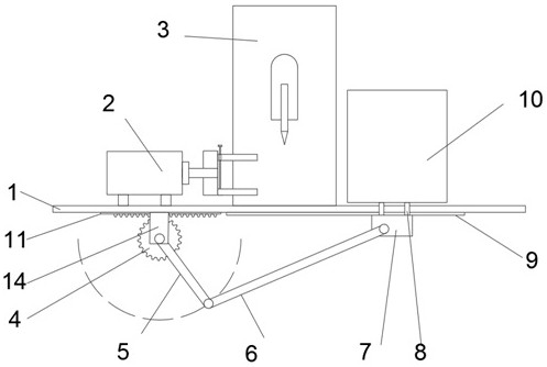
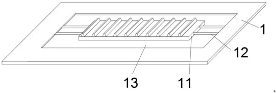
[0017] refer to Figure 1 to Figure 2 , a flying debris blocking device for parts casting, comprising a support plate 1, the left half of the upper surface of the support plate 1 is provided with a motor 2, the output end of the motor 2 is fixedly connected with a clamping mechanism, and the clamping mechanism includes a fixed block, two symmetrically arranged clamping blocks, one of which is fixedly connected to the fixed block, the other clamping block is threadedly connected with a bolt, and the bolt is rotatably connected to the clamping block at the bottom, and the middle part of the upper surface of the support plate 1 is fixedly connected with Cutting mechanis...


PUM


Abstract

The invention discloses a flying scrap blocking device for part casting. The flying scrap blocking device for part casting comprises a supporting plate, a motor is arranged on the left half portion ofthe upper surface of the supporting plate, a cutting mechanism is fixedly connected to the middle of the upper surface of the supporting plate, a moving groove is formed in the left side of the supporting plate, and a rail is fixedly connected into the moving groove. A partition plate is adopted and automatically moved, during cutting, the partition plate moves to a cutting position to block scraps, so that the harm of scrap splashing to operators is effectively avoided, and the potential safety hazard is reduced. The partition plate is automatically moved away after cutting is finished, a mold is conveniently taken out, the operation steps and time are saved, and the working efficiency is greatly improved. A rotary cutting mode is adopted for cutting, the clamped mold is driven to rotatethrough rotation of the motor, the contact surface of the mold and an electric saw is reduced, and the phenomenon that the electric saw is stuck is avoided. Besides, the cutting efficiency is improved, the operation steps and time are saved, and the working efficiency is greatly improved.

Description

technical field [0001] The invention relates to the technical field of interior decoration, in particular to a flying debris blocking device used for part casting. Background technique [0002] When the casting part is completed, there are usually excess parts remaining on the part during casting, which need to be cut off by a cutting device. The general cutting method is to use a cutting machine to cut continuous castings one by one. However, if the cutting device is used to cut the excess part of the casting, the iron filings will splash under the drive of the drill bit, and when the employee does not wear protective glasses, the splashing iron filings can easily splash on the face of the staff, especially Eyes, there is a great safety hazard, which will cause harm to the operator, and the discarded parts after cutting will fall randomly, which is not conducive to maintaining a clean working environment. Contents of the invention [0003] The purpose of the present inv...

Claims


Application Information

Patent Timeline
IPC IPC(8): B23Q11/08
CPCB23Q11/08
Inventor 不公告发明人
Owner 朕诺机械设备江苏有限公司
Why Eureka
Try Eureka