Heated offshore pipeline and method of manufacturing

A pipeline and pipe technology, which is applied to heated submarine pipelines and their manufacturing fields, can solve problems such as the consumption of steel windings or ground electrodes, and achieve the effect of reducing the amount of steel used.

Inactive Publication Date: 2003-09-10
格伦·R·萨姆纳
View PDF4 Cites 0 Cited by
  • Summary
  • Abstract
  • Description
  • Claims
  • Application Information

AI Technical Summary

Problems solved by technology

The disadvantage of using direct current is that the seawater will act as an electrolyte and the steel windings or ground electrodes will be quickly consumed by electrolysis

Method used


Image

  • Heated offshore pipeline and method of manufacturing
  • Heated offshore pipeline and method of manufacturing
  • Heated offshore pipeline and method of manufacturing

Examples


Embodiment Construction

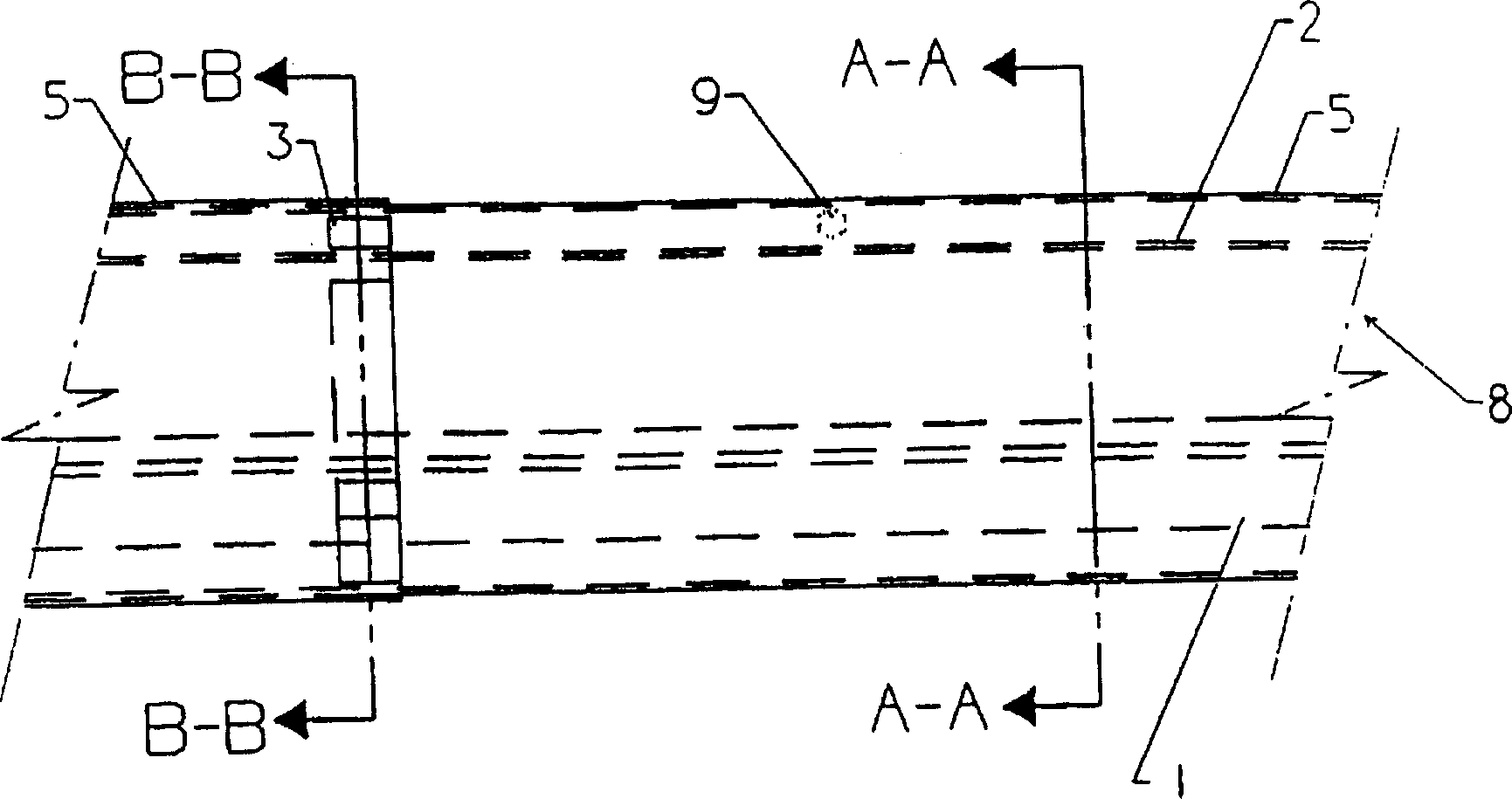
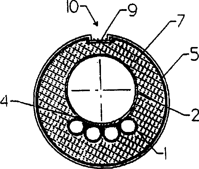
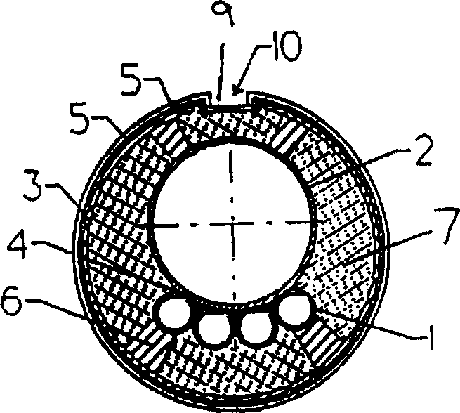
[0041] Figure 1-3 The tubing bundle is shown in a circular die. If such an arrangement is made on a flat surface, such as for towed tube bundles, such as Figure 15 As shown, some or all of the spacers can be formed to extend across the cross-section of the mold so that the mold is divided into short segments which can be top filled with insulating material. Such spacers such as Figure 15 and 16 shown. As shown in Figures 7, 10, 11, it is possible, for example, to cast the insulating material when the pipeline is inclined, but this is not required.

[0042] Such as figure 1 As shown, continuous or discontinuous pipes are used to reduce the underwater weight of pipelines or pipe bundles with wood and other lightweight materials including particles dispersed therein which are lighter than insulating compounds. If the lightweight material contains porosity, it should be strong enough to resist the static pressure of any seawater passing to it through the insulation. It d...


PUM


Abstract

A submerged marine pipeline (201) is electrically insulated from sea water and is heated by alternating current that flows through the pipeline, where the AC power supply (212) is grounded to ambient sea water (206). The insulating material is cast between an assembled length of a pipeline or bundle of pipelines and molds that are continuous, or directly to one another along and around the assembled length, before it has been placed at its final destination.

Description

technical field [0001] The present invention relates to pipelines electrically heated by an alternating current and a method of insulating submarine pipelines through which an alternating current flows through conductive pipelines insulated from sea water with a waterproof coating, and in particular to a method of applying heat insulating material after the pipes have been welded together, Therefore, various troubles caused when laying pipelines in deep sea are avoided. Background technique [0002] "Subsea" or "offset" production techniques are increasingly being used in the production of offshore oil and gas from subsea reservoirs. The technology uses subsea pipelines called "pipelines" that run on shorter routes between wellheads on the sea floor and oil gathering stations like nearby platforms. For various reasons, it is often beneficial or necessary to take measures to maintain the high temperature of the fluid flowing in the subsea pipeline. One way of doing this is t...

Claims


Application Information

Patent Timeline
Patent Type & Authority Patents(China)
IPC IPC(8): E21B17/01E21B43/01F16L53/37F16L59/14
CPCF16L59/14E21B43/01E21B17/015E21B17/01F16L53/007F16L53/37
Inventor 格伦·R·萨姆纳
Owner 格伦·R·萨姆纳
Why Eureka
Try Eureka