
Hybrid cooling system of electric drive system and vehicle

An electric drive system and hybrid cooling technology, which can be applied to the arrangement of the cooling combination of the power plant, electric components, vehicle components, etc., can solve the problems of increasing the volume and cost of the electric drive system, internal heat accumulation, and poor heat dissipation effect. , to achieve good lubrication effect, excellent heat dissipation performance, and the effect of reducing parts

Pending Publication Date: 2020-12-18
CHINA FIRST AUTOMOBILE
View PDF11 Cites 5 Cited by
  • Summary
  • Abstract
  • Description
  • Claims
  • Application Information

AI Technical Summary

Problems solved by technology

The reducer is mainly circulated and cooled by the internal lubricating oil, and the heat of the lubricating oil can only rely on the natural heat dissipation of the reducer shell to the outside, and the heat dissipation effect is not good. Cause premature failure of internal parts
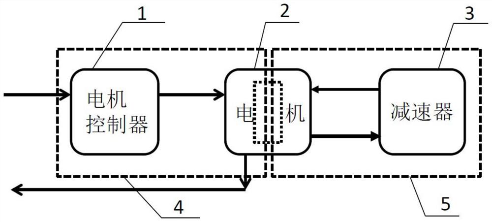
[0004] In the prior art, mostly only the motor and the reducer are considered for mixed cooling, and the motor controller is rarely considered. However, with the development trend of the integration of electric drive systems, it is necessary to comprehensively consider the motor controller, motor and reducer. Cooling requirements of the electric drive system within
In addition, at present, the mixed cooling method of oil cooling and water cooling is used in the motor at the same time, and its structure generally includes an oil cooling circulation system installed inside the motor, a water cooling system installed at the housing, and an independent heat exchange module. The module includes an external independent heat exchange oil channel and an external independent heat exchange water channel. The heat absorbed by the lubricating oil in the heat exchange oil channel is transferred to the cooling water in the heat exchange channel, and the above cooling water enters the heat sink to complete the heat exchange, but the above heat The switching device is generally installed outside the motor or reducer as an independent component, which increases the size and cost of the electric drive system and is inconvenient to install

Method used


Image

  • Hybrid cooling system of electric drive system and vehicle
  • Hybrid cooling system of electric drive system and vehicle
  • Hybrid cooling system of electric drive system and vehicle

Examples


Embodiment Construction

[0040] In order to make the purpose, technical solutions and advantages of the embodiments of the present invention clearer, the technical solutions in the embodiments of the present invention will be clearly and completely described below in conjunction with the drawings in the embodiments of the present invention. Obviously, the described embodiments It is a part of embodiments of the present invention, but not all embodiments. The components of the embodiments of the invention generally described and illustrated in the figures herein may be arranged and designed in a variety of different configurations.

[0041] Accordingly, the following detailed description of the embodiments of the invention provided in the accompanying drawings is not intended to limit the scope of the claimed invention, but merely represents selected embodiments of the invention. Based on the embodiments of the present invention, all other embodiments obtained by persons of ordinary skill in the art wi...


PUM


Abstract

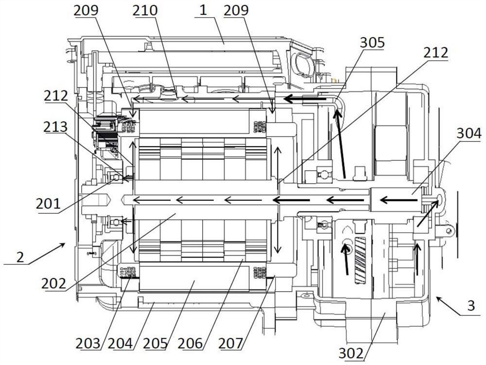
The invention relates to the technical field of cooling of electric drive systems, in particular to a hybrid cooling system of an electric drive system and a vehicle. The hybrid cooling system of theelectric drive system comprises an oil cooling system and a water cooling system. The oil cooling system comprises a speed reducer oil conveying path, a motor oil conveying path and a plurality of motor oil spraying openings, and lubricating oil in a speed reducer shell flows through the speed reducer oil conveying path and the motor oil conveying path and is sprayed into a motor shell from the motor oil spraying openings. The motor shell comprises a heat exchange area, and lubricating oil in the motor shell can flow into the heat exchange area. The water cooling system comprises a controllerheat dissipation water path and a motor shell heat dissipation water path, cooling liquid flowing through the controller heat dissipation water path is used for cooling the controller, and cooling liquid flowing through the motor shell heat dissipation water path is used for cooling the motor shell, a stator of a motor and lubricating oil in the cooling heat exchange area. No special heat exchangedevice needs to be arranged, and the size and cost of the electric drive system are reduced.

Description

technical field [0001] The invention relates to the technical field of cooling of an electric drive system, in particular to a hybrid cooling system of an electric drive system and a vehicle. Background technique [0002] Due to the development trend of integration, miniaturization, high speed and high power density of electric drive systems of new energy vehicles, the requirements for reliability, cooling and lubrication of electric drive systems are getting higher and higher. At present, the cooling of the motor controller mainly relies on the coolant to cool the power device. There are two main modes of motor heat dissipation, water-cooled motor and oil-cooled motor. The water-cooled motor relies on the circulating coolant in the water jacket to cool the stator, and the winding and rotor cannot If the motor shell is in contact, it can only rely on air heat dissipation to cool down. There is no direct liquid cooling, so that the motor cannot run at the maximum power for a ...

Claims


Application Information

Patent Timeline
IPC IPC(8): B60K11/02H02K5/20H02K9/19F16H57/04H05K7/20
CPCB60K11/02H02K5/20H02K9/19F16H57/0476F16H57/0413H05K7/20872
Inventor 刘金锋赵慧超高一赵成福张颖徐德才王宏宝
Owner CHINA FIRST AUTOMOBILE
Learn More