Motor control method, device and motor system

A motor control and controller technology, applied in the field of control, can solve problems such as winding temperature rise and motor speed characteristics poorness, achieve the effect of increasing motor speed, solving winding temperature rise, and reducing temperature

Active Publication Date: 2017-09-22
GREE ELECTRIC APPLIANCES INC
View PDF9 Cites 0 Cited by
  • Summary
  • Abstract
  • Description
  • Claims
  • Application Information

AI Technical Summary

Problems solved by technology

[0005] In view of this, the present invention provides a motor control method, device and motor system, which can effectively solve the problem of temperature rise of the motor winding under high voltage and poor motor speed characteristics under low voltage under the premise of ensuring a large voltage range for the motor. The problem

Method used


Image

  • Motor control method, device and motor system
  • Motor control method, device and motor system
  • Motor control method, device and motor system

Examples


Embodiment 1

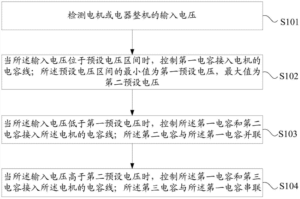
[0055] see figure 1 , figure 1 It is a flow chart of a motor control method provided by an embodiment of the present invention. Such as figure 1 As shown, the method includes:

[0056] Step S101, detecting the input voltage of the motor or the complete electrical appliance;

[0057] Specifically, the input voltage of the motor in the electrical appliance is equal to the input voltage of the electrical appliance, and any one of them can be detected.

[0058] Step S102, when the input voltage is in a preset voltage range, control the first capacitor to be connected to the capacitor line of the motor; the minimum value of the preset voltage range is the first preset voltage, and the maximum value is the second preset voltage ;

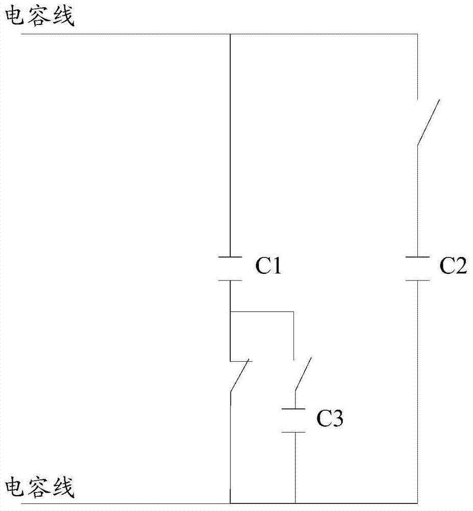
[0059] Specifically, see figure 2 , figure 2 It is a structural diagram of a motor capacitance control circuit provided by an embodiment of the present invention. Such as figure 2 As shown, the first capacitor C1 can be connected to the capaci...

Embodiment 2

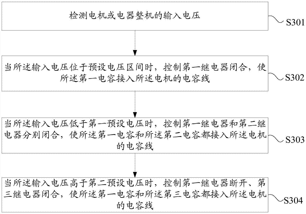
[0067] see image 3 , image 3 It is a flow chart of another motor control method provided by the embodiment of the present invention. Such as image 3 As shown, the method includes:

[0068] Step S301, detecting the input voltage of the motor or the complete electrical appliance;

[0069] Step S302, when the input voltage is within a preset voltage range, control the first relay to close, so that the first capacitor is connected to the capacitor line of the motor, and the first relay is connected in series with the first capacitor;

[0070] Step S303, when the input voltage is lower than the first preset voltage, control the first relay and the second relay to close respectively, so that both the first capacitor and the second capacitor are connected to the capacitor line of the motor; The first relay is connected in series with the first capacitor, and the second relay is connected in series with the second capacitor;

[0071] Step S304, when the input voltage is higher...

Embodiment 3

[0074] see Figure 4 , Figure 4 It is a flow chart of another motor control method provided by the embodiment of the present invention. Such as Figure 4 As shown, the method includes:

[0075] Step S401, detecting the input voltage of the motor or the complete electrical appliance;

[0076] Step S402, when the input voltage is in the preset voltage range, control the normally closed contact of the fourth relay to maintain a closed state, so that the first capacitor is connected to the capacitor line of the motor, and the normally closed contact of the fourth relay is The closed contact is connected in series with the first capacitor;

[0077] Step S403, when the input voltage is lower than the first preset voltage, control the normally closed contact of the fourth relay to maintain a closed state, connect the first capacitor to the capacitor line of the motor, and control the fifth relay The relay is closed, so that the second capacitor is connected to the capacitor lin...


PUM


Abstract

The invention discloses a motor control method, device and motor system. The method includes: detecting the input voltage of the motor or the complete electrical appliance; when the input voltage is within a preset voltage range, controlling the first capacitor to be connected to the capacitor line of the motor; the minimum value of the preset voltage range is the first A preset voltage, the maximum value of which is the second preset voltage; when the input voltage is lower than the first preset voltage, control the first capacitor and the second capacitor to connect to the capacitor line of the motor; the second The capacitor is connected in parallel with the first capacitor; when the input voltage is higher than the second preset voltage, the first capacitor and the third capacitor are controlled to be connected to the capacitor line of the motor; the third capacitor and the The first capacitor is connected in series. Adopting the technical solution provided by the invention can effectively solve the problems of temperature rise of the winding of the motor under high voltage and poor speed characteristics of the motor under low voltage under the premise of ensuring a large applicable voltage range of the motor.

Description

technical field [0001] The invention relates to the technical field of control, in particular to a motor control method, device and motor system. Background technique [0002] As a basic component of an electrical appliance, the motor's operating performance directly determines the operating status of the electrical appliance. [0003] At present, corresponding to different grid voltages, the motor winding is provided with at least two different speed gear interface circuits, and the motor winding is connected to the corresponding speed gear interface circuit through the relays on the different speed gear interface circuits. In the prior art, it is generally necessary to design a three-speed motor to realize the operation of the motor in a low-voltage environment and a high-voltage environment, that is, to operate within a set voltage range. However, just changing the gear position of the motor cannot solve the problems of the temperature rise of the winding under high volt...

Claims


Application Information

Patent Timeline
Patent Type & Authority Patents(China)
IPC IPC(8): H02P23/00H02P27/02
Inventor 李岗蔡勋涛李和坤
Owner GREE ELECTRIC APPLIANCES INC
Why Eureka
Try Eureka