

Electrochemical hydrogen pump for preparing high-pressure hydrogen
A high-pressure hydrogen and electrochemical technology, applied in the electrolysis process, electrolysis components, cells, etc., can solve the problems of low efficiency, high noise, high energy consumption, and achieve the effect of reducing cost, no noise, and high boosting efficiency
- Summary
- Abstract
- Description
- Claims
- Application Information
AI Technical Summary
Problems solved by technology
Method used
Image

Examples
Embodiment 1
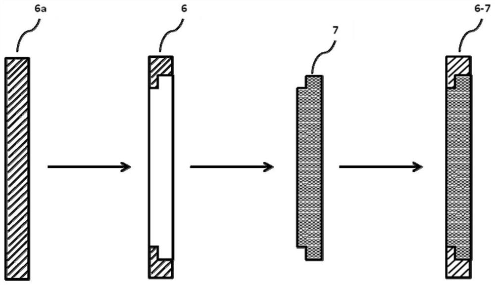
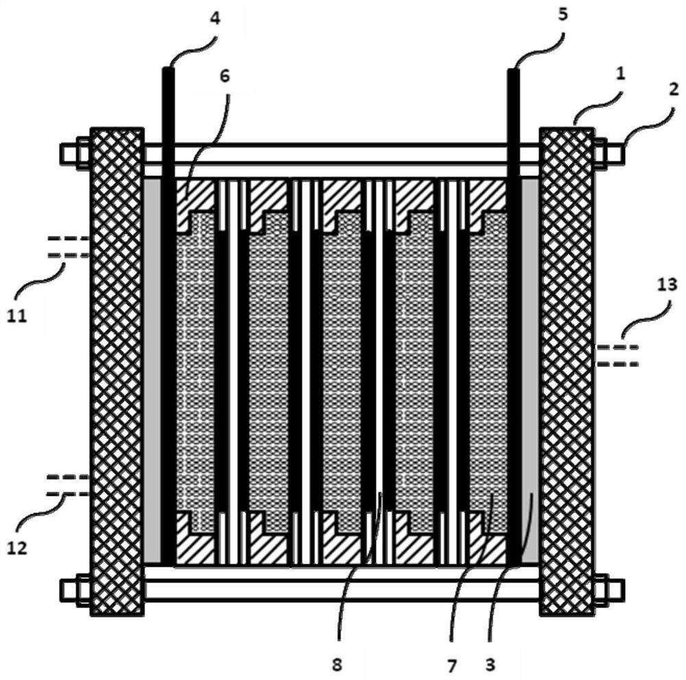
[0050] Such as figure 1 and figure 2 As shown, a low-pressure hydrogen gas inlet 11 and a low-pressure hydrogen gas outlet 12 are processed on one side of the fastening end plate 1, insulating plate 3 and positive electrode plate 4, and on the other side, the fastening end plate 1, insulating plate 3 and negative electrode plate 5 Process the high-pressure hydrogen outlet 13. Sealing is done between the fastening end plate 1 and the insulating plate 3, between the insulating plate 3 and the electrode plates 4 and 5, between the positive plate 4, the negative plate 5 and the separating and fixing plate 6. Select the separation and fixing plate original plate 6a that is consistent with the thickness of the gas-liquid transmission plate 7, and process the shape 6 with a built-in step, and process the gas-liquid transmission plate into a corresponding boss shape 7, such as figure 1 As shown, the separation and fixing plate-gas-liquid transmission plate assembly formed by the co...
Embodiment 2
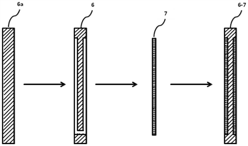
[0054] Such as image 3 and Figure 4 As shown, the difference between this embodiment and Embodiment 1 is that the air chamber components 6-7 are different. In this embodiment, the original plate 6a of the partition and fixing plate is selected, recesses 6 are processed on both sides of the partition and fixing plate, through holes 9 and 10 are processed on the partition and fixing plate, and the gas-liquid transmission plate is processed and embedded in the partition and fixing plate in the recessed platform. When a multi-stage hydrogen pump is used and multiple partitions and fixed plates are used, the gas-liquid channels processed on adjacent partitioned fixed plates should be staggered so that the gas and liquid can fully flow. Under the premise of ensuring good support, there can be one or more gas-liquid channels.
PUM
 Abstract
Description
Claims
Application Information