Ironing machine cleaning system and control method thereof

A cleaning system and ironing machine technology, applied in the field of ironing, can solve the problems of weakened heating effect, prolonged heating time, poor ironing effect, etc., so as to improve the descaling effect, improve the service life, and improve the ironing effect. Effect

Active Publication Date: 2020-12-18
ZHEJIANG YUELI ELECTRICAL
View PDF9 Cites 0 Cited by
  • Summary
  • Abstract
  • Description
  • Claims
  • Application Information

AI Technical Summary

Problems solved by technology

However, when the ironing machine is used for a long time, a large amount of scale will appear inside the ironing machine, which makes the heating time of the water longer, the heating effect is greatly weakened, and the steam generation is seriously insufficient, resulting in poor ironing effect
[0004] The traditional method is to disassemble the ironing machine, add cleaning agent, clean the scale inside the ironing machine, and then assemble the ironing machine, which is very troublesome.

Method used


Image

  • Ironing machine cleaning system and control method thereof
  • Ironing machine cleaning system and control method thereof
  • Ironing machine cleaning system and control method thereof

Examples


Embodiment 1

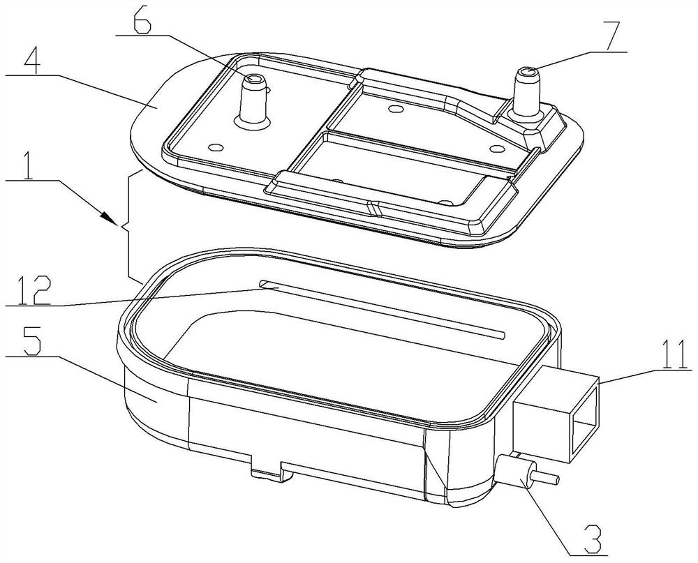
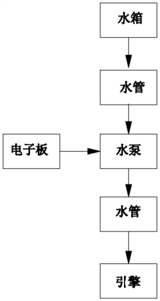
[0035] Embodiment one is basically as attached Figure 1-5 Shown: as figure 1 The cleaning system of an ironing machine shown includes an ironing machine body 1, an electronic board 2, a water pump, a water tank, a water pipe, and an engine 3. The ironing machine body 1 includes an upper cover 4 and a lower casing 5, and the upper cover 4 There are water inlet holes 6 and steam outlet holes 7 at the left and right ends of the engine respectively; the engine 3 includes heat pipes, which are embedded in the bottom of the lower casing 5 by die-casting technology, and the heat pipes can be Jshg type U-shaped pipes, and the heat pipes can be Connect to household power supply by wire.

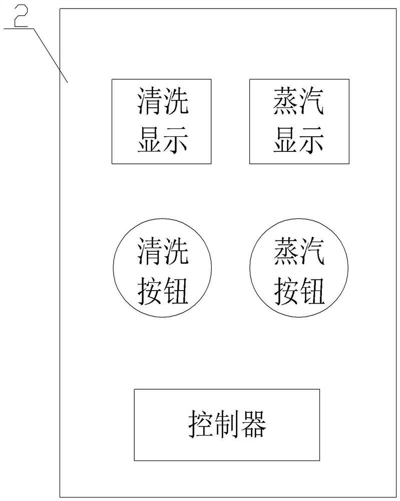
[0036] The electronic board 2 and the water tank are installed on the outside of the lower housing 5, and the water pump is installed on the water pipe between the water tank and the water inlet 6. like image 3 As shown, the electronic board 2 includes a cleaning display, a cleaning button, a ste...

Embodiment 2

[0043] On the basis of Example 1, as Figure 4 As shown, the cleaning system also includes a cleaning mechanism. The cleaning mechanism includes a servo motor 8, a screw 9 and a descaling block 10. A frame 11 with openings at both ends is welded on the body 1 of the ironing machine. The servo motor 8 is fixed on the iron body 1 by bolts. In the frame 11, the model of the servo motor 8 can be MR-J2S-100A; the screw 9 is located in the ironing machine body 1, the right end of the screw 9 is welded to the output shaft of the servo motor 8, and the left end of the screw 9 is connected to the lower casing 5 The side wall rotation connection.

[0044] Have threaded hole on the descaling block 10, and the descaling block 10 is threadedly connected with screw rod 9 by threaded hole; Figure 5 As shown, the inner wall of the lower housing 5 is provided with a "convex"-shaped slideway 12, the slideway 12 includes a limiting groove 13 and a flow groove 14; a block is welded on the desca...

Embodiment 3

[0054] Different from Embodiments 1 and 2, the cleaning system in this embodiment includes an ironing machine body 1, a water pump, a water tank, a water pipe, an engine 3 and a cleaning mechanism. The setting method is the same as in the first and second embodiments. The working steps are to manually start the water pump first, then pump water for 1 min, and then the heating pipe, the water pump and the cleaning mechanism work at the same time for 2 minutes. After the heat pipe works alone for 1min, the cleaning process is completed.


PUM


Abstract

The invention relates to the field of ironing, in particular to an ironing machine cleaning system and a control method thereof. The ironing machine cleaning system comprises an ironing machine body,an electronic board, a water pump, a water tank, a water pipe and an engine, a water inlet hole and a steam outlet are formed in the two ends of the ironing machine body correspondingly, the engine isarranged in the ironing machine body, the electronic board and the water tank are installed on the outer side of the ironing machine body, and the water pump is installed on the water pipe between the water tank and the water inlet hole. By the adoption of the technical scheme, the interior of the ironing machine is cleaned conveniently.

Description

technical field [0001] The invention relates to the field of ironing, in particular to a cleaning system of an ironing machine and a control method thereof. Background technique [0002] The ironing machine was invented in the 18th century as a kind of washing machine. At the end of the 19th century, the steam engine was introduced into the design of washing machine, so the industrial steam ironing machine appeared. [0003] The steam ironing machine is provided with a heating tube inside the ironing machine to turn water into steam and spray it out, which is beneficial to improve the ironing effect. However, when the ironing machine is used for a long time, a large amount of scale will appear inside the ironing machine, which makes the heating time of the water longer, the heating effect is greatly weakened, and the steam generation is seriously insufficient, which leads to poor ironing effect. [0004] The traditional method is to disassemble the ironing machine and add c...

Claims


Application Information

Patent Timeline
Patent Type & Authority Applications(China)
IPC IPC(8): D06C15/00D06B1/02D06B23/30
CPCD06C15/00D06B1/02D06B23/30Y02B40/00
Inventor 方国洪马灯亮
Owner ZHEJIANG YUELI ELECTRICAL
Why Eureka
Try Eureka