Mechanism for controlling valve opening and closing, variable valve device and method

A valve and switch technology, which is applied in the field of vehicles, can solve the problems that the engine performance cannot be guaranteed, and the variable valve structure cannot be installed, so as to achieve the effect of guaranteeing the braking effect in the cylinder, reducing the pressure and reducing the emission.

Active Publication Date: 2020-12-18
LONGKOU ZHONGYU THERMAL MANAGEMENT SYST SCIAND TECH
View PDF7 Cites 1 Cited by
  • Summary
  • Abstract
  • Description
  • Claims
  • Application Information

AI Technical Summary

Problems solved by technology

[0006] For the consideration of energy saving of diesel engine, all countries are paying attention to improving the combustion process. Atkinson cycle is recognized as one of the main means to realize high-efficiency thermodynamic cycle of diesel engine. The inventor found that the existing device for realizing in-cylinder braking is a single Due to the limitation of the installation space, there is currently a problem of interference between the in-cylinder brake device and the variable valve structure in the installation space, so the variable valve structure cannot be installed under the premise of the in-cylinder brake installation. Thereby, the performance of the engine cannot be guaranteed

Method used


Image

  • Mechanism for controlling valve opening and closing, variable valve device and method
  • Mechanism for controlling valve opening and closing, variable valve device and method
  • Mechanism for controlling valve opening and closing, variable valve device and method

Examples


Embodiment 1

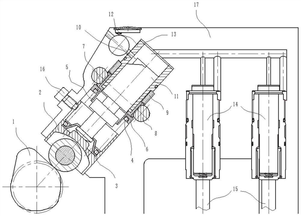
[0044] In a typical embodiment of the present invention, refer to figure 1 and Figure 8 As shown, the mechanism for controlling the valve switch includes a plunger sleeve 12, a plunger is arranged in the plunger sleeve, one end of the plunger is set beyond the bottom end of the plunger, and a rotatable control sleeve 5 is arranged at the bottom end of the plunger. The plunger is provided with an oil control profile, and the inner side of the control sleeve is provided with a control groove for the plunger to slide up and down, and the control groove of the control sleeve is engaged with the peripheral side of the plunger, and the control sleeve can drive the plunger to rotate together through the control groove.

[0045] One end of the plunger is set beyond the control sleeve, and the plunger sleeve is provided with an oil inlet and outlet hole and an oil outlet hole on the side near the other end of the plunger. An oil chamber is formed between the plug sleeves, and the end...

Embodiment 2

[0062] This embodiment discloses a variable valve device, including a camshaft, an intake valve and / or an exhaust valve, and the intake valve and / or exhaust valve are connected to the mechanism for controlling the valve switch described in Embodiment 1 , the camshaft is provided with at least one cam, the cam can be in contact with the rolling body, and the camshaft drives the corresponding cam to rotate, thereby pushing the plunger to move relative to the plunger sleeve through the rolling body, thereby controlling the mechanism for controlling the valve switch and the intake air valve and / or exhaust valve communication.

[0063] Further, the cam not only sets the first projection 19, refer to Figure 7 As shown, the exhaust cam is also provided with a second protrusion 20, the protrusion amplitude of the second protrusion is the same as or different from that of the first protrusion, and there is a gap between the second protrusion and the first protrusion. The set distance...


PUM


Abstract

The invention discloses a mechanism for controlling opening and closing of a valve, a variable valve device and a method. The problem of poor in-cylinder braking effect in the prior art is solved, thebeneficial effect of realizing in-cylinder braking is achieved, the specific solution of the mechanism for controlling the opening and closing of the valve comprises a plunger sleeve, a rotatable control sleeve is arranged on the plunger sleeve part in the circumferential direction, plungers are arranged in the plunger sleeve and the control sleeve, oil control molded lines are arranged in the plungers, protrusions capable of moving along the oil control molded lines of the plungers are arranged on the inner sides of the control sleeves, one ends of the plungers exceed the control sleeve, oilinlet and return holes and oil outlet holes are formed in the side portions, close to the other ends of the plungers, of the plunger sleeve, oil cavities are formed between the end parts of the plungers and the plunger sleeve in the plunger sleeve, the ends, away from the oil outlet holes, of the plungers are arranged in a shell, a rolling body is movably arranged in the shell, the rolling body can move along the inner side of the shell under the action of external force and can make contact with the end parts of the plungers.

Description

technical field [0001] The invention relates to the vehicle field, in particular to a mechanism for controlling a valve switch, a variable valve device and a method. Background technique [0002] The statements in this section merely provide background information related to the present invention and do not necessarily constitute prior art. [0003] Emission standards above National VI require that the engine test cycle adopts WHSC / WHTC cycle. Compared with the ESC / ETC cycle widely used in the past, there are obvious differences in the distribution of working conditions and average temperature, and the WHSC / WHTC cycle is more focused on low speed and low load. For the emission detection of working conditions, in order to meet the requirements of emission regulations, diesel engine factories must increase the exhaust temperature of WHSC / WHTC cycle, improve the conversion efficiency of nitrogen oxides, and reduce the harmful emissions of diesel engines. Adjusting the intake a...

Claims


Application Information

Patent Timeline
Patent Type & Authority Applications(China)
IPC IPC(8): F01L1/344F01L13/00F01L13/06F01L1/047F02D13/02F02D13/04
CPCF01L1/3442F01L13/0015F01L13/06F01L1/047F02D13/0223F02D13/0242F02D13/04F01L2001/34423
Inventor 王兆宇郑建松徐军领李光明
Owner LONGKOU ZHONGYU THERMAL MANAGEMENT SYST SCIAND TECH
Why Eureka
Try Eureka