
Pressing device and optical detection equipment

A pressing device and optical detection technology, applied in the field of optical detection, can solve problems affecting the accuracy of machine detection, affecting the imaging quality of cameras, and unable to adjust PCB boards, so as to improve detection accuracy, uniform pressure, and reduce processing costs. Effect

Active Publication Date: 2020-12-18
SUZHOU VEGA TECH CO LTD
View PDF4 Cites 1 Cited by
  • Summary
  • Abstract
  • Description
  • Claims
  • Application Information

AI Technical Summary

Problems solved by technology

Due to the PCB's own material or processing, it will cause local warping, which will affect the imaging quality and thus the accuracy of machine detection. Therefore, it is necessary to install a flat optical glass pressure plate to flatten the PCB board.
However, the existing pressing device cannot be adjusted according to the warpage and protrusion of different PCB boards. If the local pressing of the PCB board is uneven, it will affect the imaging quality of the camera, and then affect the detection accuracy.

Method used


Image

  • Pressing device and optical detection equipment
  • Pressing device and optical detection equipment
  • Pressing device and optical detection equipment

Examples


Embodiment Construction

[0032] In the description of the present invention, it should be noted that the terms "center", "upper", "lower", "left", "right", "vertical", "horizontal", "inner", "outer" etc. The indicated orientation or positional relationship is based on the orientation or positional relationship shown in the drawings, and is only for the convenience of describing the present invention and simplifying the description, rather than indicating or implying that the referred device or element must have a specific orientation, or in a specific orientation. construction and operation, therefore, should not be construed as limiting the invention. In addition, the terms "first" and "second" are used for descriptive purposes only, and should not be understood as indicating or implying relative importance. Wherein, the terms "first position" and "second position" are two different positions.

[0033] Unless otherwise clearly specified and limited, the terms "mounted", "connected", "connected" and ...


PUM


Abstract

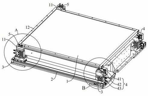
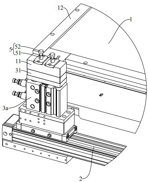
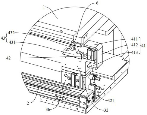
The invention discloses a pressing device and optical detection equipment, and belongs to the technical field of optical detection. The optical detection equipment comprises the pressing device, the pressing device comprises a cover plate, a plurality of jacking mechanisms, a first supporting structure and a pressing mechanism, and the cover plate is used for optical detection; the jacking mechanism is used for driving the cover plate to ascend and descend. The pressing mechanism comprises a driving part and a pressure bearing part, the driving part is connected to the output end of the jacking mechanism, the pressure bearing part is connected to the cover plate, and the driving part is used for driving the pressure bearing part to press downwards so as to drive the cover plate to press downwards. The pressing device can be suitable for flattening PCBs warped or raised in different degrees, and the detection precision of the optical detection equipment is improved.

Description

technical field [0001] The invention relates to the technical field of optical detection, in particular to a pressing device and optical detection equipment. Background technique [0002] Automatic optical inspection equipment is based on the principle of optics, collects images through cameras, and checks and analyzes product quality after image processing. Due to the PCB's own material or processing, it will cause local warping, which will affect the imaging quality and thus the accuracy of machine detection. Therefore, it is necessary to install a flat optical glass pressure plate to flatten the PCB board. However, the existing pressing device cannot be adjusted according to the warpage and protrusion of different PCB boards. If the local pressing of the PCB board is uneven, the imaging quality of the camera will be affected, and then the detection accuracy will be affected. Contents of the invention [0003] An object of the present invention is to provide a pressing ...

Claims


Application Information

Patent Timeline
Patent Type & Authority Applications(China)
IPC IPC(8): G01N21/88G01N21/01
CPCG01N21/01G01N21/8851G01N2021/8887
Inventor 陈林锋高亮常远
Owner SUZHOU VEGA TECH CO LTD
Learn More