Clapper-type relay with plurality of static springs

A snap-fit, relay technology, applied in relays, electromagnetic relays, electromagnetic relay details and other directions, can solve the problems of static reed 301 flatness drop, large base volume, poor product assembly consistency, etc., to avoid flatness drop. , Improve the injection molding yield and improve the effect of assembly accuracy

Pending Publication Date: 2020-12-18
XIAMEN HONGFA AUTOMOTIVE ELECTRONICS CO LTD
View PDF0 Cites 1 Cited by
  • Summary
  • Abstract
  • Description
  • Claims
  • Application Information

AI Technical Summary

Problems solved by technology

[0003] One is that it is not conducive to the miniaturization of the product. This is because the base 400 needs to provide fixed support for the static spring 300. The fixing of the static spring usually needs to meet a certain pull-out force requirement. When the base 400 is inserted into the static spring piece 301, if the base 400 If the wall thickness of the slot 401 is too thin, it will cause cracking of the base and insufficient creepage distance between the static springs. Therefore, the part of the base where the static spring is inserted needs to have a certain plastic wall thickness to prevent the static spring from being inserted into the base. Cause cracking of the base and insufficient creepage distance, so that the volume of the base will be larger
[0004] The second is that it is inconvenient to manufacture the product. Since the base 400 needs to be provided with multiple slots 401, the base has many plastic walls, which makes the base structure more complicated. The product design must consider the base structure to prevent plastic shrinkage during injection molding. Deformation and injection molding dissatisfaction, also need to consider the wall thickness balance of the base structure, which will increase the difficulty of product production
[0005] The third is that the consistency of product assembly is relatively poor. Since multiple static springs 300 are inserted into the base 400 respectively, it is easy to cause a drop in flatness between the static spring pieces 301 during insertion.

Method used


Image

  • Clapper-type relay with plurality of static springs
  • Clapper-type relay with plurality of static springs
  • Clapper-type relay with plurality of static springs

Examples


Embodiment

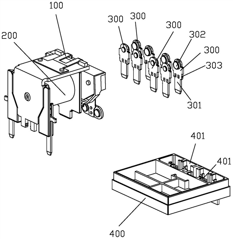
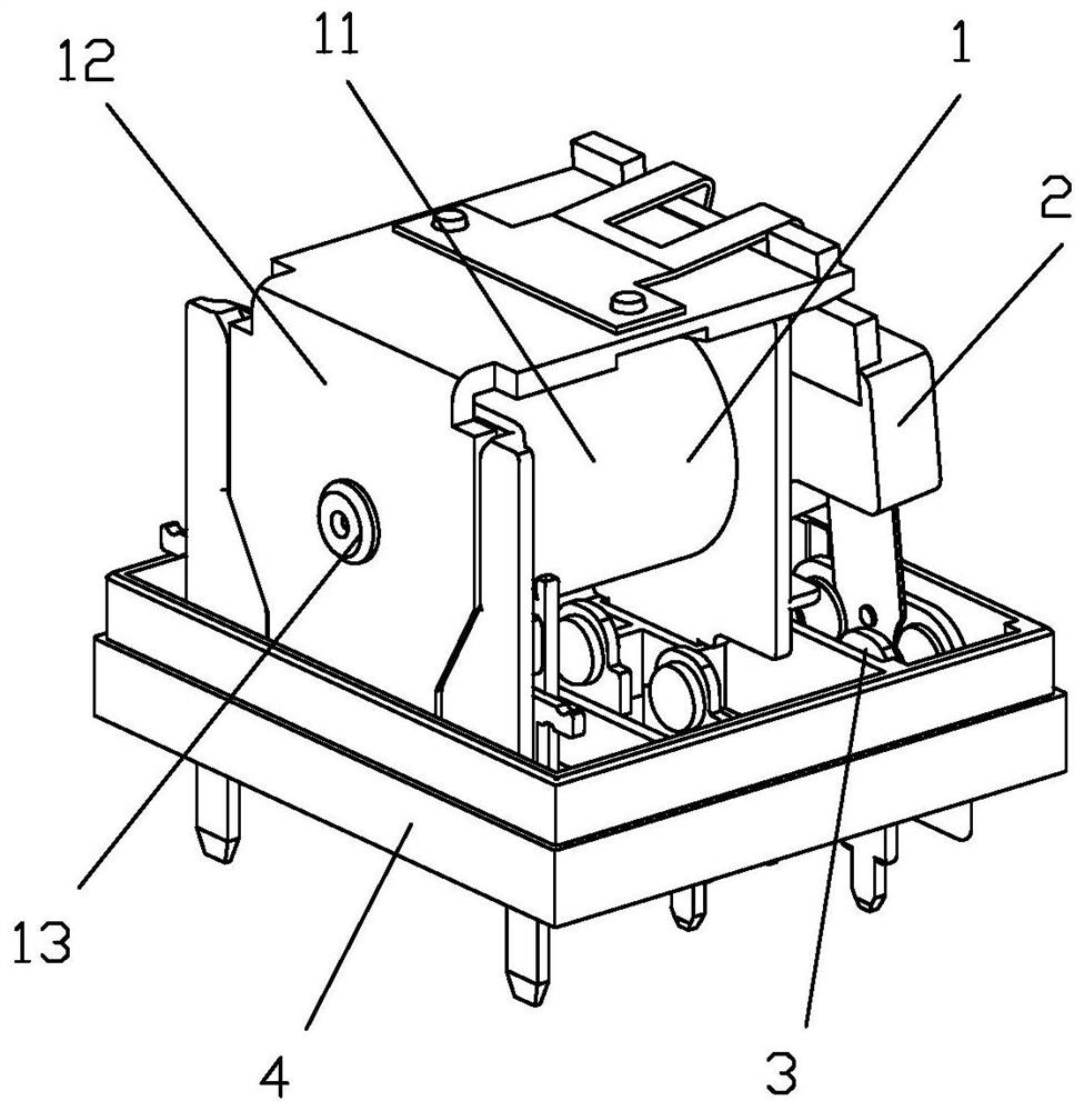
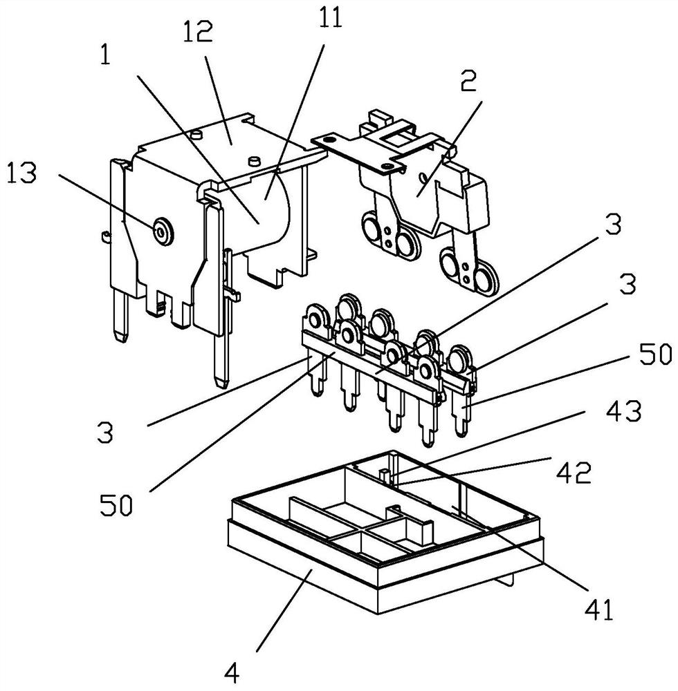
[0041] see Figure 2 to Figure 15 As shown, a clapping relay with a plurality of static springs of the present invention includes a magnetic circuit part 1, a moving spring armature part 2, a plurality of static springs 3 and a base 4; the static spring 3 includes a static reed 31 and a Static contact 32, the top of described static reed 31 fixes described static contact 32, and the bottom of described static reed 31 is set as lead-out pin 311; Described a plurality of static springs 3 are divided into a static spring group or a Above static spring group, in the present embodiment, has eight static springs 3, is divided into two static spring groups, and each static spring group contains four static springs 3, and wherein a static spring group is as normally open static spring and moving The other static spring group is used as a normally closed static spring to cooperate with the moving spring. The two static spring groups have the same structure and are installed in opposite...


PUM


Abstract

The invention discloses a clapper-type relay with a plurality of static springs. The clapper-type relay comprises the plurality of static springs and a base, each static spring comprises a static reedand a static contact; the plurality of static springs are divided into one static spring group or more than one static spring group; the static reeds in each static reed set are arranged in a row inthe width direction of the static reeds, the static reeds in the static reed set are connected into an integral assembly in a mutual insulation mode through a first injection molding piece formed through injection molding, and the first injection molding piece wraps the middle portions of the static reeds. A mounting groove is formed in the base, the integral assembly is arranged in the mounting groove, convex bracts are respectively arranged at two side ends of the integral assembly, and when the integral assembly is arranged in the mounting groove, the convex bracts at the two side ends of the integral assembly are in interference fit with the mounting groove. The relay has the characteristics that the product volume is small, the miniaturization is convenient to realize, the manufacturing difficulty of the product can be reduced, and the assembly consistency is improved.

Description

technical field [0001] The invention relates to the technical field of relays, in particular to a snap-on relay with a plurality of static springs. Background technique [0002] A clapping type relay of the prior art includes a plurality of static springs, such as figure 1 as shown, figure 1 It is an exploded schematic diagram of the three-dimensional structure of a snap-in relay in the prior art. This snap-in relay includes a moving spring armature part 100, a magnetic circuit part 200, a plurality of static springs 300 and a base 400. The magnetic circuit part 200 is mounted on the base, and the moving The spring armature part 100 is matched with the magnetic circuit part 200. The static spring 300 is composed of a static spring 301 and a static contact 302. The static contact 302 is fixed on the static spring 301. The static spring 300 is usually inserted on the base 400. The base 400 is provided with a plurality of slots 401 for inserting the static reeds 301 respectiv...

Claims


Application Information

Patent Timeline
Patent Type & Authority Applications(China)
IPC IPC(8): H01H50/56H01H50/02H01H50/04H01H50/24H01H50/36H01H50/58
CPCH01H50/02H01H50/04H01H50/24H01H50/36H01H50/56H01H50/58
Inventor 吴灵勇
Owner XIAMEN HONGFA AUTOMOTIVE ELECTRONICS CO LTD
Why Eureka
Try Eureka