
High-isolation power divider and power combiner

A high-isolation and power combiner technology, applied in the field of radio frequency and microwave, can solve the problems of difficult power combination, affecting system stability, poor isolation between ports of double-probe transition power combiner, etc., and achieves easy connection and system Integration, favorable miniaturization design, and compact structure

Active Publication Date: 2020-12-18
LEIHUA ELECTRONICS TECH RES INST AVIATION IND OF CHINA
View PDF16 Cites 3 Cited by
  • Summary
  • Abstract
  • Description
  • Claims
  • Application Information

AI Technical Summary

Problems solved by technology

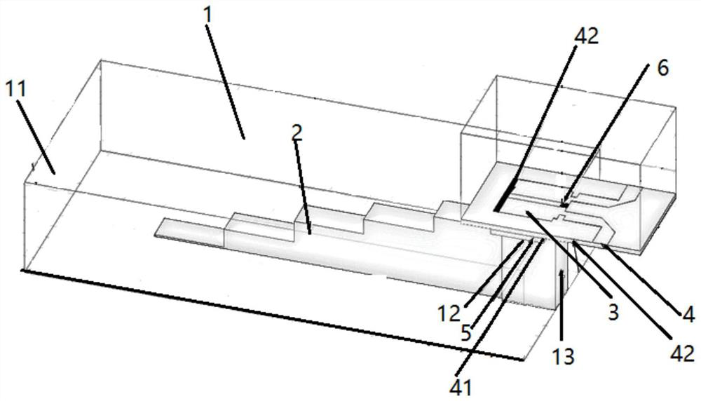
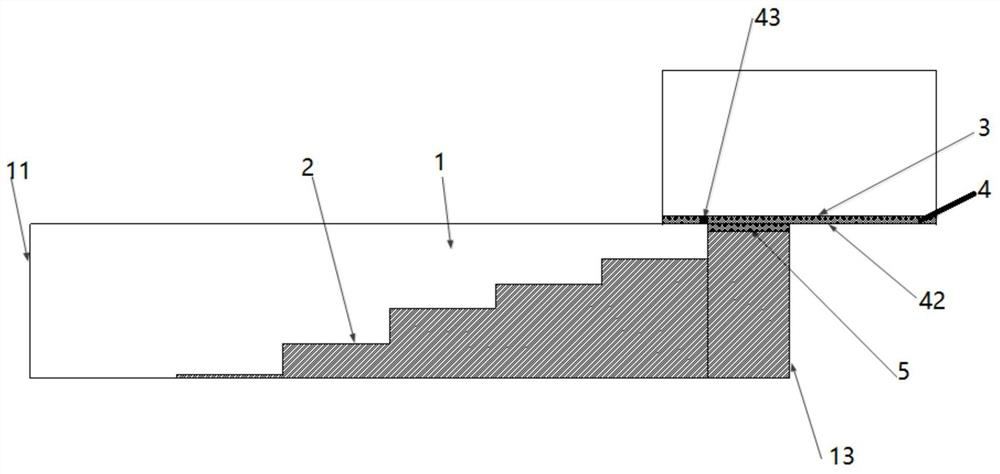
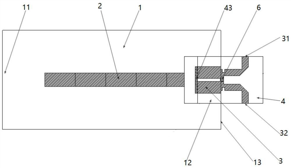
[0003] In view of the poor isolation between the ports of the double-probe transitional combiner, which affects the stability of the system when it is used for power synthesis, and the common ridge waveguide transition has the disadvantage that it is not easy to achieve power synthesis, this patent uses the ridge waveguide to double microstrip lines The coupling transition method realizes the transition from the waveguide to the microstrip and at the same time realizes the distribution / combination of power, and introduces an isolation resistor between the double microstrip lines, thereby realizing the isolation between the sub-ports of the two microstrip lines, and at the same time Improved VSWR performance of split ports

Method used


Image

  • High-isolation power divider and power combiner
  • High-isolation power divider and power combiner
  • High-isolation power divider and power combiner

Examples


Embodiment Construction

[0024]In order to make the purpose, technical solutions and advantages of the implementation of this application clearer, the technical solutions in the implementation of the application will be described in more detail below in conjunction with the drawings in the implementation of the application. In the drawings, the same or similar reference numerals indicate the same or similar elements or elements with the same or similar functions. The described implementations are part of the implementations of the present application, rather than all of the implementations. The following embodiments described with reference to the drawings are exemplary, and are intended to explain the present application, but should not be understood as a limitation to the present application. Based on the implementation manners in this application, all other implementation manners obtained by those of ordinary skill in the art without creative work shall fall within the protection scope of this applicatio...


PUM


Abstract

The invention belongs to the technical field of radio frequency microwaves, and particularly relates to a high-isolation power divider / combiner. The power divider / combiner comprises a waveguide cavity, the waveguide cavity comprises a first end and a second end which are opposite to each other, the first end is provided with a waveguide port for power input or output, the second end is closed by aconductive shell to form a waveguide short-circuit surface, a window is arranged above the waveguide cavity adjacent to the waveguide short-circuit surface, and through the window, the waveguide cavity is coupled with the microstrip circuit; a microstrip circuit comprises a substrate, two paths of microstrip lines are arranged on the upper end surface of the substrate, and the lower end surface of the substrate comprises a section of joint part used for covering the window of the waveguide cavity; and a waveguide filling medium fills the window of the waveguide cavity and is used for connecting the substrate of the microstrip circuit with the waveguide ridge of the waveguide cavity. According to the structure, power distribution / combination is directly realized while waveguide microstripconversion is carried out, good isolation is realized, the structure is more compact, and miniaturization design of the system is facilitated.

Description

Technical field[0001]This application belongs to the field of radio frequency and microwave technology, and particularly relates to a high isolation power splitting power combiner.Background technique[0002]In microwave and millimeter wave, microstrip line is a very important form of transmission in microwave integrated circuits. However, at present, many microwave and millimeter wave test systems and device interfaces use rectangular waveguides. Therefore, waveguide-microstrip converters are widely used. It is used in the detection of microwave and millimeter wave monolithic integrated circuits and hybrid circuits, as well as the connection of waveguides and planar circuits, so that there is a good matching transition between the two transmission lines. The waveguide-microstrip transition technology has become one of the key technologies for system realization and has been widely studied. Common waveguide-microstrip transition technologies mainly include: probe transition, ridge wav...

Claims


Application Information

Patent Timeline
IPC IPC(8): H01P5/16
CPCH01P5/16
Inventor 王朝阳王默然李军
Owner LEIHUA ELECTRONICS TECH RES INST AVIATION IND OF CHINA
Learn More