Slaughter house sewage treatment device
A sewage treatment device and slaughterhouse technology, applied in water/sewage treatment, water/sewage treatment equipment, water/sludge/sewage treatment, etc., can solve the problem of large labor capacity, easy accumulation of suspended matter in a large area, and influence on sewage treatment Efficiency and other issues
- Summary
- Abstract
- Description
- Claims
- Application Information
AI Technical Summary
Problems solved by technology
Method used
Image

Examples
Embodiment 1
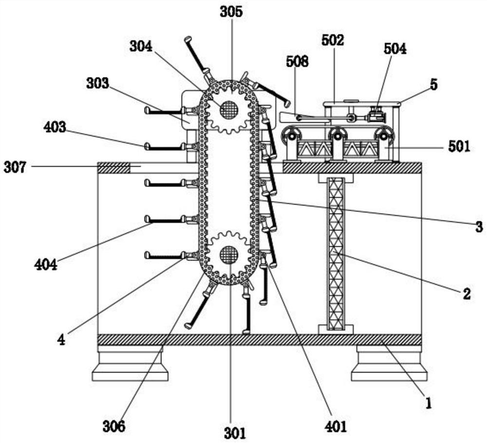
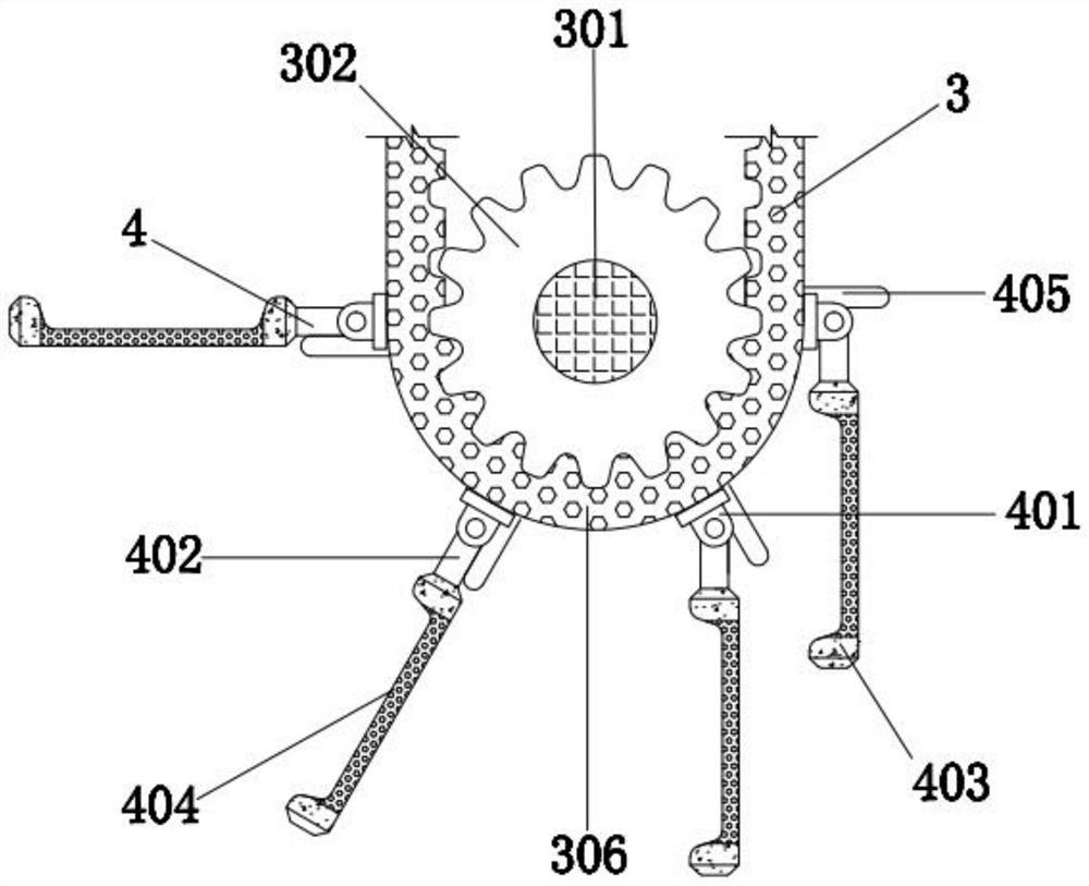
[0031] A sewage treatment device for a slaughterhouse, comprising a water pipeline 1 and a grid 2, the grid 2 is installed on the right side of the inner wall of the water pipeline 1, and a blockage reduction mechanism 3 is provided on the left side of the water pipeline 1, and the blockage reduction mechanism 3 includes the first cross bar 301, the first roller 302, the bracket 303, the second cross bar 304, the second roller 305, the filter belt 306, the channel 307 and the motor 308, the first cross bar 301 is located in the water pipeline 1 On the left side of the interior, the first cross bar 301 is connected to the water pipeline 1 through a sealed bearing. The model of 308 is ECMA-E11320RS, and the power line of the motor 308 is connected to the external power supply device. The motor 308 is fixedly connected to the outer wall of the water pipeline 1 through the mounting bracket, and the outer wall of the first cross bar 301 is sleeved with the first roller. 302, the in...
Embodiment 2
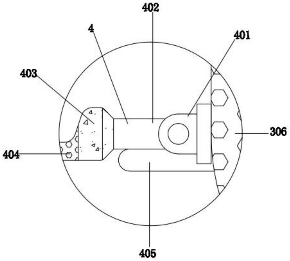
[0033] As an option, see Figure 1-3, a slaughterhouse sewage treatment device, the outer surface of the filter belt 306 is provided with a collection mechanism 4, the collection mechanism 4 includes a bump 401, a short rod 402, a groove plate 403, a filter hole 404 and a support plate 405, and a plurality of bumps 401 The outer surface of the filter belt 306 is evenly and equidistantly fixed, and the outside of the bump 401 is provided with a short rod 402. The contact surface of the plate 403 and the short rod 402 is fixedly connected, the lower surface of the groove plate 403 is provided with a plurality of filter holes 404, the inner diameter of the filter hole 404 is 10-20 mm, and the bottom end of the outer wall of the short rod 402 is provided with a support plate 405. The upper surface of the plate 405 is pressed against the contact surface of the short bar 402, the support plate 405 is fixedly connected with the contact surface of the bump 401, and the vertical sectio...
Embodiment 3
[0036] As an option, see figure 1 , 4 And 5, the slaughterhouse sewage treatment device, the top right side of the outer wall of the water pipeline 1 is provided with an auxiliary mechanism 5, the auxiliary mechanism 5 includes a conveyor belt 501, a top plate 502, a leg 503, an electric push rod 504, a bracket 505, a block 506, U-shaped bar 507, inclined plate 508 and trapezoidal bar 509, conveyor belt 501 is installed on the right side of the outer wall top of water pipeline 1, top plate 502 is provided above conveyor belt 501, and the left and right ends of the lower surface of top plate 502 are all fixedly connected with Outrigger 503, the bottom end of the outrigger 503 is fixedly connected with the contact surface of the water pipeline 1, the right side of the lower surface of the top plate 502 is provided with an electric push rod 504, the model of the electric push rod 504 is TJC-C1-452MM, and the electric push rod 504 The power line of the push rod 504 is connected t...
PUM
 Abstract
Description
Claims
Application Information
 - R&D
- Intellectual Property
- Life Sciences
- Materials
- Tech Scout
- Unparalleled Data Quality
- Higher Quality Content
- 60% Fewer Hallucinations
Browse by: Latest US Patents, China's latest patents, Technical Efficacy Thesaurus, Application Domain, Technology Topic, Popular Technical Reports.
© 2025 PatSnap. All rights reserved.Legal|Privacy policy|Modern Slavery Act Transparency Statement|Sitemap|About US| Contact US: help@patsnap.com