Production-transportation integrated continuous reaction device for hydrate

A reaction device and hydrate technology, applied in gas fuel, petroleum industry, fuel and other directions, can solve the problems of retardation, shorten the induction period, low gas storage rate, etc., to increase the conversion rate, increase the gas-liquid contact area, improve the The effect of gas storage rate

Active Publication Date: 2020-12-22
QINGDAO UNIV OF SCI & TECH
View PDF23 Cites 1 Cited by
  • Summary
  • Abstract
  • Description
  • Claims
  • Application Information

AI Technical Summary

Problems solved by technology

Among them, the stirring method is the most direct and simple method, which can break the mass transfer limitation of the gas-liquid interface and effectively shorten the induction period by continuously updating the interface. However, the stirring efficiency gradually decreases with the continuous formation of natural gas hydrate, resulting in a

Method used


Image

  • Production-transportation integrated continuous reaction device for hydrate
  • Production-transportation integrated continuous reaction device for hydrate
  • Production-transportation integrated continuous reaction device for hydrate

Examples


Example Embodiment

[0018] Example 1:

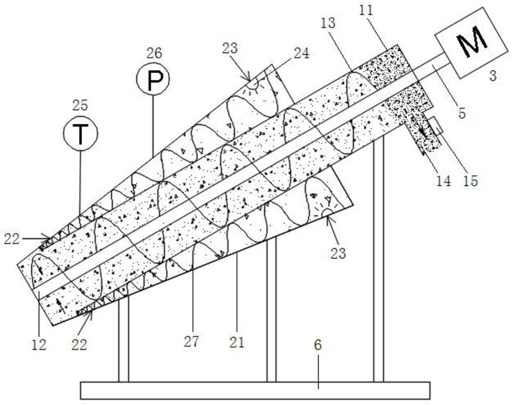
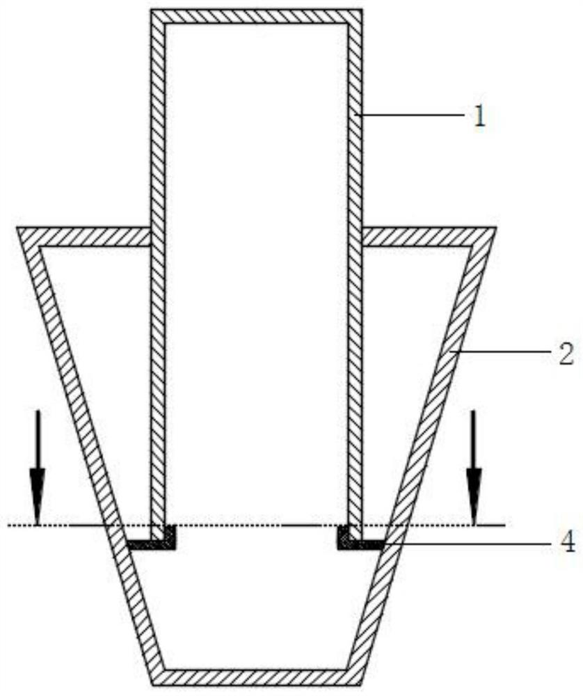
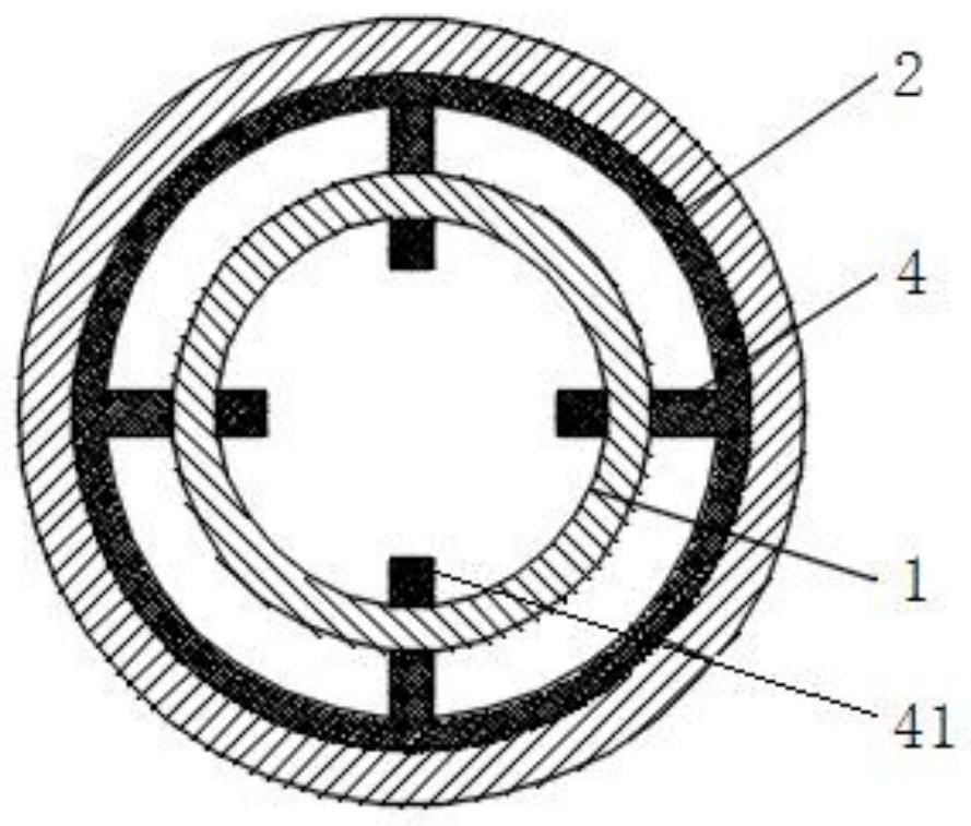
[0019] The main structure of the hydrate production-transport integrated continuous reaction device involved in this embodiment includes an inner screw reactor 1, an outer screw reactor 2, a motor 3, a clasp 4 and a magnetic transmission rod 5; One end of the spiral reactor 1 extends into the interior of the outer spiral reactor 2 with an inverted trapezoidal cross section, and the other end of the inner spiral reactor 1 is connected to the motor 3; the inner spiral reactor 1 and the outer spiral reactor 2 pass through the clasp 4 connection, the central axis of the inner spiral reactor 1 and the outer spiral reactor 2 coincide, and the inner spiral reactor 1 and the motor 3 are connected through a magnetic transmission rod 5 .

[0020] The main structure of the internal spiral reactor 1 involved in this embodiment includes an inner cylinder 11, a stirring rod 12, an internal spiral blade 13, a discharge port 14 and a ball valve 15; the inner cylinder 11 wi...

Example Embodiment

[0024] Example 2:

[0025] When the hydrate production-transport integrated continuous reaction device involved in this embodiment is used, the upper part of the inner cylinder 11, the 1 / 3 length of the outer cylinder 21 and the 2 / 3 length of the outer cylinder 21 are respectively connected to the support 6, and the support 6 While supporting the inner spiral reactor 1 and the outer spiral reactor 2, it has an angle adjustment function, and the inclination angle of the inner spiral reactor 1 and the outer spiral reactor 2 is adjusted to 30° (the adjustment range of the support 6 is 0°~ 90 °); send gas through the air inlet 22 to sweep the inner spiral reactor 1 and the outer spiral reactor 2, get rid of air, when the internal temperature of the inner spiral reactor 1 and the outer spiral reactor 2 reaches the set When the reaction temperature is reached, gas is sent in again through the air inlet 22, so that the internal pressure of the inner screw reactor 1 and the outer scre...


PUM


Abstract

The invention belongs to the technical field of production and application of natural gas hydrate, and particularly relates to a production-transportation integrated continuous reaction device for hydrate. The device structurally comprises an inner spiral reaction kettle, an outer spiral reaction kettle, a motor, a clamping ring and a magnetic transmission rod, wherein the inner spiral reaction kettle and the outer spiral reaction kettle are assembled in a nesting mode. A spraying method is introduced into the outer spiral reaction kettle, and micro-droplets are generated by utilizing the spraying method; through the buffering effect of external spiral blades, a gas-liquid contact area is increased, so the falling speed of the micro-droplets is reduced, the dispersion degree of the micro-droplets is increased, the conversion time of the micro-droplets is prolonged, the conversion time of hydrate is prolonged, and a conversion rate and a gas storage rate are increased; and the generatedhydrate is output through the conveying function of stirring rods and inner spiral blades, and secondary reinforced conversion is conducted in the process, so the conversion rate is further increased, the gas storage rate is increased, and continuous, rapid, efficient and continuous production and conveying of the natural gas hydrate are achieved.

Description

Technical field: [0001] The invention belongs to the technical field of natural gas hydrate production and application, and in particular relates to a hydrate production-transport integrated continuous reaction device. Background technique: [0002] After entering the modern society, the manufacturing industry has ushered in a golden stage of development, the economy is developing rapidly, and the energy consumption is increasing day by day, especially the high consumption of coal. In the long run, economic development will be limited by energy shortages. In order to avoid excessive dependence on energy imports and reduce environmental pollution, it is imperative to use abundant, clean and efficient energy to replace coal and oil in production on a large scale. [0003] Due to its excellent characteristics, natural gas has taken an increasing proportion in energy supply in recent years. Natural gas has problems such as huge regional differences in distribution and seasonal ...

Claims


Application Information

Patent Timeline
IPC IPC(8): C10L3/08
CPCC10L3/08
Inventor 王飞张国栋
Owner QINGDAO UNIV OF SCI & TECH
Why Eureka
Try Eureka