Lower oscillation sliding vane jet flow stroke-increasing hydraulic oscillator

A hydraulic oscillator and jet technology, which is used in vibration drilling, vibration generating devices, wellbore/well components, etc., can solve the problems of short service life, complex structure, and many rotating parts, and achieve long service life and output efficiency. High, few moving parts effect

Active Publication Date: 2020-12-22
SINOPEC OILFIELD EQUIP CORP +1
View PDF8 Cites 1 Cited by
  • Summary
  • Abstract
  • Description
  • Claims
  • Application Information

AI Technical Summary

Problems solved by technology

The problem is that the pressure loss of this solution is high, usually reaching 3~4 Mpa, and the service life is usually less than 500 hours, and the price of the screw motor is very high, such as the structure in Chinese patent document CN205778542U
2. The jet structure uses the vortex cavity to generate vibration and the periodic change of the pressure medium to generate high-frequency vibration, but the pressure loss of this scheme is only 0.2-0.3 Mpa, the frequency is high, and the frequency cannot be controlled
The problem with this solution is that the structure is relatively complex, there are too many rotating parts, the cost is high, the loss is high, and the turbine rotor rotates at a high speed, which makes the output frequency of the tool high, difficult to control, and has a short service life.

Method used


Image

  • Lower oscillation sliding vane jet flow stroke-increasing hydraulic oscillator
  • Lower oscillation sliding vane jet flow stroke-increasing hydraulic oscillator
  • Lower oscillation sliding vane jet flow stroke-increasing hydraulic oscillator

Examples


Embodiment Construction

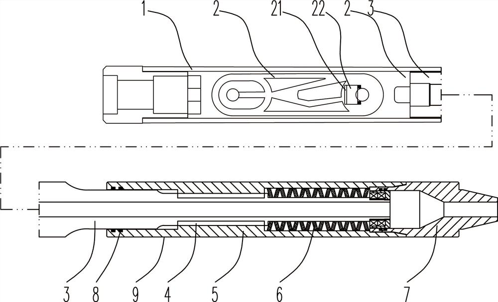
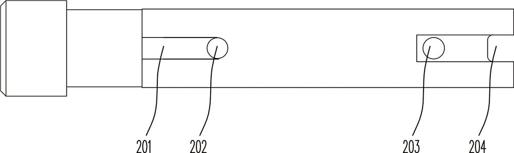
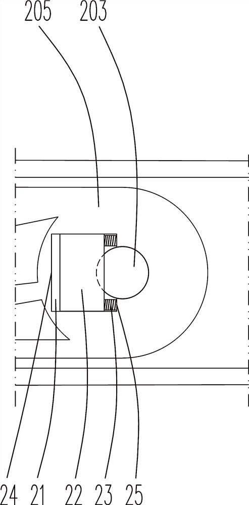
[0026] Such as Figure 1~4 Among them, a lower oscillating sliding vane jet flow extended range hydraulic oscillator, the outer sleeve 1 is fixed with a vortex cavity body 2, the vortex cavity body 2 is used to generate vibration, and an inlet hole 205 is provided at one end of the vortex cavity body 2, The other end of the vortex cavity body 2 is provided with an outlet hole 203, the outlet hole 203 is located at the center of the vortex cavity 205, and a chute 21 is provided on one side of the vortex cavity 203, and a slideway 21 is provided in the chute 21 to slide along the axial direction. One end of the stroke of the movable slider 22 partially covers the outlet hole 203 , and the other end of the stroke is completely away from the outlet hole 203 to alternately limit the flow section of the outlet hole 203 . Due to this structure, due to the vibration generated by the vortex cavity body 2, the vibration direction is along the axial direction of the outer sleeve 1, and t...


PUM


Abstract

The invention provides a lower oscillation sliding vane jet flow stroke-increasing hydraulic oscillator. A vortex cavity is fixedly arranged in an outer sleeve and used for generating vibration; a flow inlet hole is formed in one end of the vortex cavity, and a flow outlet hole is formed in the other end of the vortex cavity and located in the circle center position of the vortex cavity; a slidinggroove is formed in one side of the flow outlet hole and internally provided with a movable sliding block sliding in the axial direction; and one end of the stroke of the movable sliding block partially covers the flow outlet hole, and the other end of the stroke of the movable sliding block completely leaves the flow outlet hole so as to alternately limit the through-flow section of the flow outlet hole. By the adoption of the scheme that the movable sliding block is arranged in the vortex cavity, the movable sliding block is driven by vibration of the vortex cavity to reciprocate, and therefore the through-flow area of a flow inlet channel is changed, the vibration amplitude of the vortex cavity is increased, the vibration frequency is reduced, and then the vibration form meeting the underground construction requirement is obtained, namely the proper amplitude and vibration frequency are obtained. According to the structure of the lower oscillation sliding vane jet flow stroke-increasing hydraulic oscillator, the number of movable components is small, the service life is long, the pressure loss of a drive component is extremely low, and the output efficiency is high.

Description

technical field [0001] The invention relates to the field of oil drilling and production equipment, in particular to a lower-oscillating sliding vane jet flow-extending hydraulic oscillator. Background technique [0002] At present, drilling in oil fields has developed from vertical wells to directional wells and horizontal wells. Drilling tools are usually close to the lower side well wall. The friction of drilling tools on the well wall is too large, which affects the drilling efficiency and makes it difficult to transmit the drilling pressure to the drill bit. In order to overcome this defect, a solution of a hydraulic oscillator has appeared in the prior art, through which the static friction of the drilling tool is changed into dynamic friction to reduce friction. Existing hydraulic oscillators generally have three structures. 1. Screw motor structure, which drives the rotor to rotate through the screw, so that the flow section of the hole between the rotor and the stat...

Claims


Application Information

Patent Timeline
IPC IPC(8): E21B7/24E21B28/00
CPCE21B7/24E21B28/00
Inventor 钱伟强余长柏蒋洪亮李红许剑宋满华类歆商艳红
Owner SINOPEC OILFIELD EQUIP CORP
Why Eureka
Try Eureka