
Flank anchor rod with one-way valves and for extruding soil body

A technology of one-way valves and flanks, which is applied in the installation of bolts, earthwork drilling, dikes, etc., can solve the problems of weak bearing capacity, small contact area and working range, and small strength of solidified slurry, so as to improve bearing capacity, The effect of expanding the contact area and working range

Pending Publication Date: 2020-12-22
CREEC WUHAN SURVEY DESIGN & RES
View PDF0 Cites 2 Cited by
  • Summary
  • Abstract
  • Description
  • Claims
  • Application Information

AI Technical Summary

Problems solved by technology

[0004] The present invention provides a kind of anchor rod with flanks for extruding soil with a one-way valve, which solves the problem in the prior art of "stop grouting and wait for a small amount of anchor rods with flanks to stop grouting in the protrusion of the flanks." When solidifying, sometimes the slurry in the flank protrusions will flow back, resulting in the final solidified slurry in the flank protrusions being small and not strong enough, which will also lead to weaker bearing capacity for slopes, tunnels, and dams.” , "Due to the small contact area and working range between the existing anchor rods and the surrounding soil, resulting in weaker bearing capacity for slopes, tunnels, and dams"

Method used


Image

  • Flank anchor rod with one-way valves and for extruding soil body
  • Flank anchor rod with one-way valves and for extruding soil body
  • Flank anchor rod with one-way valves and for extruding soil body

Examples


Embodiment Construction

[0052] The following is attached Figure 1-8 The principles and features of the present invention are described, and the examples given are only used to explain the present invention, and are not used to limit the scope of the present invention. In the following paragraphs the invention is described more specifically by way of example with reference to the accompanying drawings. Advantages and features of the present invention will be apparent from the following description and claims. It should be noted that all the drawings are in a very simplified form and use imprecise scales, and are only used to facilitate and clearly assist the purpose of illustrating the embodiments of the present invention.

[0053] It should be noted that when a component is said to be "fixed" to another component, it can be directly on the other component or there can also be an intervening component. When a component is said to be "connected" to another component, it may be directly connected to ...


PUM


Abstract

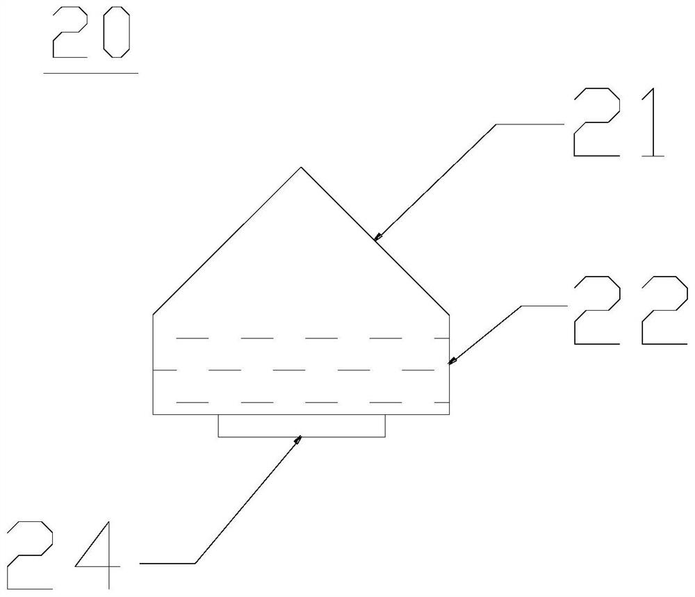
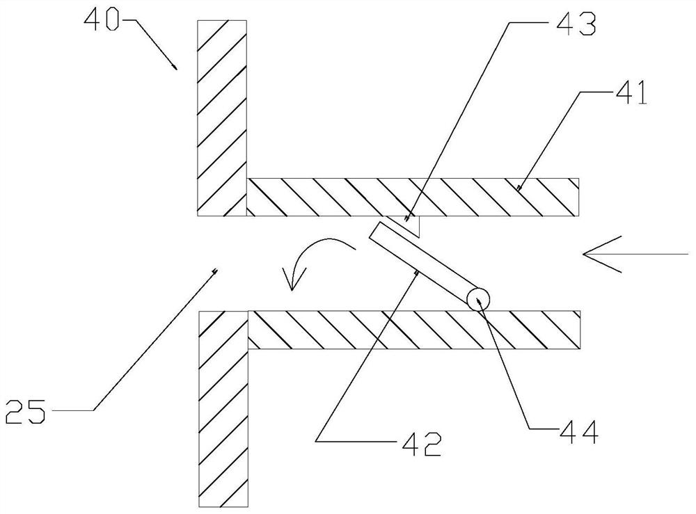
The invention relates to a flank anchor rod for extruding a soil body. The flank anchor rod comprises a straight inserting rod body, a grouting groove is formed in the straight inserting rod body, flank protrusions are arranged along the grouting groove, each flank protrusion is made of a telescopic material and is hollow, and a grouting hole is formed in the communication position between the first end of each flank protrusion and the grouting groove. One-way valves only allowing grouts to flow from the grouting groove to inner cavities of the flank protrusions through the grouting holes arearranged at the grouting holes, the flank protrusions are arranged on the straight inserting rod body wall in a penetrating mode, an initial state of the flank protrusions is a compressed state, and when the grouts are injected into the grouting groove, the flank protrusions extend outwards to be in an opened state. The one-way valves only allowing the grouts to flow from the grouting groove to the inner cavities of the flank protrusions through the grouting holes are arranged at the grouting holes, the grouts cannot flow into the grouting groove from the inner cavities of the flank protrusions in the reverse direction, the grouts in the flank protrusions are prevented from flowing reversely, and the final solidified grout amount in the flank protrusions is guaranteed, so that the strengthof the grouts is high the bearing capacity to side slopes, tunnels and dam bodies is high.

Description

technical field [0001] The invention relates to the field of electrical engineering, in particular to a bolt with side wings for extruding soil with a check valve. Background technique [0002] Anchor rod, English "Bolt"; "bolting (accurate title)"; "anchor (early title)" is the most basic part of roadway support in contemporary coal mines. It strengthens the surrounding rock of the roadway together, making the surrounding rock Support yourself. Existing anchor rods are not only used in mines, but also in engineering technology for main body reinforcement of slopes, tunnels, and dam bodies. [0003] The structure of the existing bolts is relatively simple, that is, a long straight rod is inserted into difficult formations such as silt and silt soil to perform main body reinforcement for slopes, tunnels, and dam bodies. The contact area and working range of the surrounding soil are small, resulting in weak bearing capacity for slopes, tunnels, and dams. In addition, when g...

Claims


Application Information

Patent Timeline
IPC IPC(8): E21D21/00E21D20/02E02D5/74E02D17/20E02B3/10
CPCE21D21/0026E21D21/0093E21D20/02E02D5/74E02D17/20E02B3/10
Inventor 段俊峰肖宇松刘昌裕查京屏郝翀马建军邹向农熊涛张立辉
Owner CREEC WUHAN SURVEY DESIGN & RES
Learn More