Top-mounted structure of heat exchanger of electric regenerative furnace

A heat exchanger and electric heat storage technology, applied in heat exchange equipment, heating methods, electric heating systems, etc., can solve problems such as unfavorable system heat energy exchange effect, affecting the efficiency of electric heat storage furnace, affecting equipment safety and stability, etc.

Pending Publication Date: 2020-12-22
SHENYANG SHIJIE ELECTRIC
View PDF0 Cites 0 Cited by
  • Summary
  • Abstract
  • Description
  • Claims
  • Application Information

AI Technical Summary

Problems solved by technology

When the required power of the electric heat storage furnace is very large, its floor area and the construction and installation site that can be provided often form a contradiction. If the height of the heat storage b

Method used


Image

  • Top-mounted structure of heat exchanger of electric regenerative furnace

Examples


Embodiment Construction

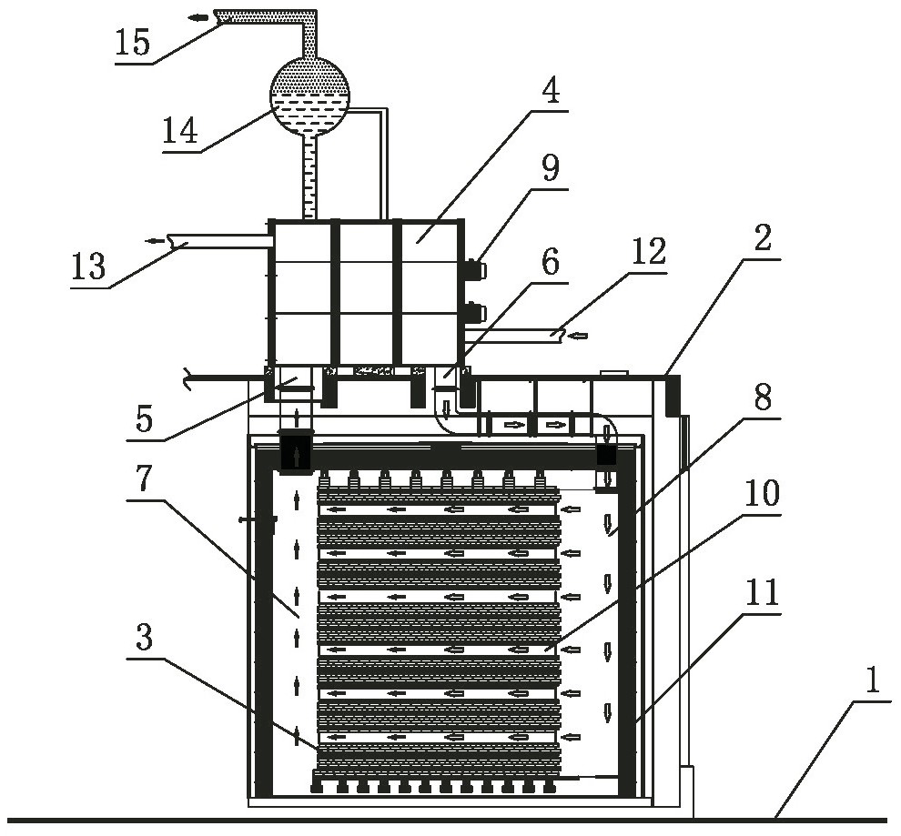
[0011] The specific embodiments of the present invention will be described in detail below with reference to the accompanying drawings. The following descriptions are only for demonstration and explanation, and do not limit the present invention in any form.

[0012] like figure 1 As shown, 1 in the figure is a ground floor, 2 is a second floor floor, 3 is an electric heat storage body with a heat storage body insulation layer 11, a high temperature wind zone 7, and a low temperature wind zone 8, 4 is a heat exchanger, 9 is a circulating fan; the electric heat accumulator is set on the ground 1 on the first floor that meets the load requirements, and the light-weight heat exchanger 4 and the circulating fan 9 are placed on the second floor 2 on the top of the electric heat accumulator. The second-floor floor slab 2 has a structure with sufficient strength and bearing capacity, and is a second-floor floor slab with sufficient overall waterproof performance to prevent the second...


PUM


Abstract

The invention relates to a top-mounted structure of a heat exchanger of an electric regenerative furnace. The top-mounted structure of the heat exchanger of the electric regenerative furnace comprisesan electric heat accumulator, the heat exchanger and a circulating fan, and is technically characterized in that the electric heat accumulator is arranged on the first ground; the heat exchanger andthe circulating fan are placed on the second floor; holes are formed in the second floor; one end of an air inlet channel is connected to an air inlet of the heat exchanger; the other end of the air inlet channel is connected with a high-temperature air area in an electric regenerative furnace body to form a high-temperature air inlet channel; one end of an air return channel is connected to an air return port of the heat exchanger; the other end of the air return channel is connected with a low-temperature warm air area in the electric regenerative furnace body to form a low-temperature air channel; a water supplementing and returning channel and a hot water output channel are connected onto the heat exchanger; a steam pocket is arranged at the top of the heat exchanger; and a steam output channel is further arranged on the steam pocket. The top-mounted structure of the heat exchanger of the electric regenerative furnace fundamentally solves the problem of potential safety hazards incentralized heating of office buildings and residential buildings. Therefore, on the premise of ensuring safe and reliable operation of the equipment, the problem of overlarge occupied area of a super-power electric regenerative furnace equipment system is solved.

Description

technical field [0001] The invention relates to the technical field of an electric regenerative furnace, in particular to a top-mounted structure of a heat exchanger of an electric regenerative furnace. Background technique [0002] Heat exchanger is one of the key components of electric regenerative furnace. In the conventional electric regenerative furnace system, the heat exchanger is usually placed on the side of the furnace body and is on the same plane as the regenerative body of the electric regenerative furnace, which makes the entire system occupy a slightly larger area; The exchanger is placed at the lower part of the regenerator, but such a structure often has potential safety hazards, especially when the power of the equipment is large, the volume and weight of the regenerator of the electric regenerative furnace are even larger, and the potential safety hazards are even more prominent, especially for office Central heating of buildings and residential buildings...

Claims


Application Information

Patent Timeline
IPC IPC(8): F24D13/00F24D15/02F24D19/00F28D7/00F28F1/10
CPCF24D13/00F24D15/02F24D19/00F28D7/00F28F1/10
Inventor 朱建新
Owner SHENYANG SHIJIE ELECTRIC
Why Eureka
Try Eureka