IGBT module internal defect monitoring method and circuit based on gate charge change

A module internal and monitoring circuit technology, applied in the direction of measuring electrical variables, measuring electricity, measuring devices, etc., can solve the problems of high sampling frequency, short-circuit current IGBT module potential hazards, unfavorable industrial field practical application, etc., to achieve accurate evaluation , easy to implement, and highly integrated

Active Publication Date: 2020-12-22
CHONGQING UNIV
View PDF10 Cites 3 Cited by
  • Summary
  • Abstract
  • Description
  • Claims
  • Application Information

AI Technical Summary

Problems solved by technology

For multi-chip IGBT modules, due to the inconsistency of the temperature of each chip, this method of ensuring a constant current during monitoring and obtaining the junction temperature of the module during the monitoring process has certain limitations on the monitoring of bonding wire defects in IGBT modules. The short-circuit current method is to use the same short-circuit current at each temperature point in the transfer characteristics of the IGBT module. The short-circuit current decreases with the increase of the IGBT module bonding wire defect and is not affected by temperature, but the short-circuit current Whether it is a potential hazard to the IGBT module or the power electronic equipment is relatively large; the gate switch signal can be used to monitor the defect state of the bonding wire of the multi-chip IGBT module, but these switch characteristic quantities are easily affected by noise, and require Sampling equipment has a high sampling frequency, which is not conducive to practical application in industrial sites

Method used


Image

  • IGBT module internal defect monitoring method and circuit based on gate charge change
  • IGBT module internal defect monitoring method and circuit based on gate charge change
  • IGBT module internal defect monitoring method and circuit based on gate charge change

Examples


Embodiment Construction

[0051] The present invention will be further described below in conjunction with the accompanying drawings and embodiments.

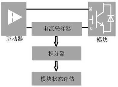
[0052] The internal defect monitoring method of the IGBT module based on the change of the gate charge, based on the fact that the gate electrical signal of the IGBT module will be affected by the change of its internal parameters due to the aging of the IGBT module during the switching process, by monitoring the IGBT module during the switching process The gate electrical signal is used to evaluate the health status of the current IGBT module.

[0053] In this way, due to the influence of internal stress and external complex working conditions on the IGBT module during operation, the internal parameters or structure of the IGBT module will change, the module will age, and the safety and reliability will decrease, which makes the IGBT module in the switching process. The gate electrical signal changes, thus providing conditions for the health status mon...


PUM


Abstract

The invention discloses an IGBT module internal defect monitoring method and circuit based on gate charge change. The method is based on the characteristic that a gate electric signal of an IGBT module in a switching process is affected by the internal parameter change of the IGBT module due to the aging of the IGBT module; a health state of the IGBT module at the current period is evaluated by monitoring a gate pole electric signal of the IGBT module in the switching process; specifically, the gate charge of the IGBT module is taken as a monitoring object, and the internal defect condition ofthe current IGBT module is evaluated by monitoring the change of the gate charge of the IGBT module in the operation process; and the gate charge information obtained in a plurality of switching periods is continuously accumulated to amplify defects in the IGBT module. According to the method, the IGBT module can be conveniently monitored under the condition that the IGBT module is not disassembled, meanwhile, it can be ensured that the health state of the IGBT module can be accurately evaluated under normal work of the IGBT module, and reliability of the module and the system is improved.

Description

technical field [0001] The invention relates to the technical field of power electronics, in particular to a method for monitoring defects in an internal branch of an IGBT module, in particular to a method and a circuit for monitoring internal defects in an IGBT module based on gate charge changes. Background technique [0002] Power electronic devices have been widely used in new energy power generation, traffic traction, aerospace and other fields. Improving the reliability of power electronic devices can meet stricter safety and cost requirements. As a general-purpose power semiconductor device, an insulated gate bipolar transistor (insulated gate bipolar transistor, IGBT) module is widely used in power electronic devices with wide power levels. In order to improve the flow capacity of the power module and reduce the cost of use, the bonded wire packaged IGBT module is considered to be a promising solution to increase the capacity of the power module. However, complex an...

Claims


Application Information

Patent Timeline
Patent Type & Authority Applications(China)
IPC IPC(8): G01R31/26G01R31/27
CPCG01R31/2642G01R31/275
Inventor 王凯宏周雒维孙鹏菊黄旭杜雄
Owner CHONGQING UNIV
Why Eureka
Try Eureka