Resonator and forming method thereof

A resonator and piezoelectric technology, applied in piezoelectric/electrostrictive/magnetostrictive devices, piezoelectric/electrostrictive device manufacturing/assembly, impedance network, etc., can solve the problem of difficult integration of RF front-end chips, filtering The problem of large size of the device can be solved, and the effect of improving the forming quality, improving performance and saving cost can be achieved.

Active Publication Date: 2020-12-22
NINGBO SEMICON INT CORP
View PDF6 Cites 9 Cited by
  • Summary
  • Abstract
  • Description
  • Claims
  • Application Information

AI Technical Summary

Problems solved by technology

However, both filters are large in size and difficult to integrate into RF front-end chips

Method used


Image

  • Resonator and forming method thereof
  • Resonator and forming method thereof
  • Resonator and forming method thereof

Examples


Embodiment Construction

[0029] It can be seen from the background art that at present, a film bulk acoustic resonator (Film Bulk Acoustic Resonator, FBAR) is widely used. But the performance of the resonators formed so far is not good.

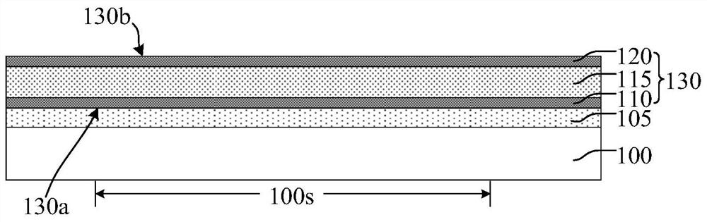
[0030] Specifically, the current manufacturing process of thin film bulk acoustic resonators is usually to form a groove in the substrate, form a sacrificial layer in the groove, and then sequentially form a piezoelectric stack structure on the sacrificial layer, and in order to release the For the sacrificial layer, it is usually necessary to form a release hole through the piezoelectric stack structure, and use the release hole to remove the sacrificial material layer in the groove to finally form a cavity.

[0031] Wherein, the step of forming the sacrificial layer generally includes: forming a sacrificial material layer in the groove, the sacrificial material layer is also formed on the substrate; grinding and removing the sacrificial material layer higher than t...


PUM


Abstract

The invention relates to a resonator and a forming method thereof, and the forming method of the resonator comprises the steps: forming a piezoelectric laminated structure on a first substrate, the piezoelectric laminated structure comprises a first region, and the surface, in contact with the first substrate, of the piezoelectric laminated structure is a first front surface; forming a sacrificiallayer covering the piezoelectric laminated structure on the first region; providing a second substrate; forming a bonding layer on the second substrate, the face, making contact with the second substrate, of the bonding layer is a second front face, and the face, opposite to the second front face, of the bonding layer is a second back face; attaching the second back surface of the bonding layer to the sacrificial layer and the piezoelectric laminated structure exposed out of the sacrificial layer, so that the bonding layer covers the side wall of the sacrificial layer and fills between the second substrate and the piezoelectric laminated structure; removing the first substrate to expose the first front surface of the piezoelectric laminated structure; forming a release hole penetrating through the piezoelectric laminated structure or forming a release hole penetrating through the second substrate, wherein the release hole exposes the sacrificial layer; and removing the sacrificial layer through the release hole to form a cavity. The method of the invention is beneficial to improving the performance of the resonator.

Description

technical field [0001] The invention relates to the field of semiconductors, in particular to a resonator and a forming method thereof. Background technique [0002] With the development of mobile communication technology, the amount of mobile data transmission is also increasing rapidly. Therefore, under the premise of limited frequency resources and the use of as few mobile communication devices as possible, improving the transmission power of wireless power transmitting devices such as wireless base stations, micro base stations or repeaters has become a problem that must be considered. The requirements for filter power in the front-end circuit of the equipment are also getting higher and higher. [0003] At present, the high-power filters in wireless base stations and other equipment are mainly cavity filters, and their power can reach hundreds of watts. In addition, some devices use dielectric filters, and their average power can reach more than 5 watts. However, the ...

Claims


Application Information

Patent Timeline
Patent Type & Authority Applications(China)
IPC IPC(8): H03H9/17H03H9/02H03H3/02H03H9/54
CPCH03H9/171H03H9/02007H03H3/02H03H9/54H03H2003/023H03H9/173H03H2003/021H10N30/05H10N30/073H10N30/086H10N30/872H10N30/10516
Inventor 杨国煌
Owner NINGBO SEMICON INT CORP
Why Eureka
Try Eureka