Waste metal pelleting machine

A technology of pelletizing machine and waste, which is applied in the field of waste metal recycling equipment, which can solve the problems of low processing capacity of metal pelletizing machine and irregular shape of metal pellets, and achieve the effect of saving internal space, occupying a large space, and reducing gaps

Pending Publication Date: 2020-12-25
河南百瑞德环保科技有限公司
View PDF0 Cites 2 Cited by
  • Summary
  • Abstract
  • Description
  • Claims
  • Application Information

AI Technical Summary

Problems solved by technology

[0005] The object of the present invention is to provide a metal scrap pelletizing machine capable of producing metal clusters with small size and regular shape, so as to solve the problem of low processing capacity and irregular shape of metal pellets produced in the prior art. question

Method used


Image

  • Waste metal pelleting machine
  • Waste metal pelleting machine
  • Waste metal pelleting machine

Examples


Embodiment 1

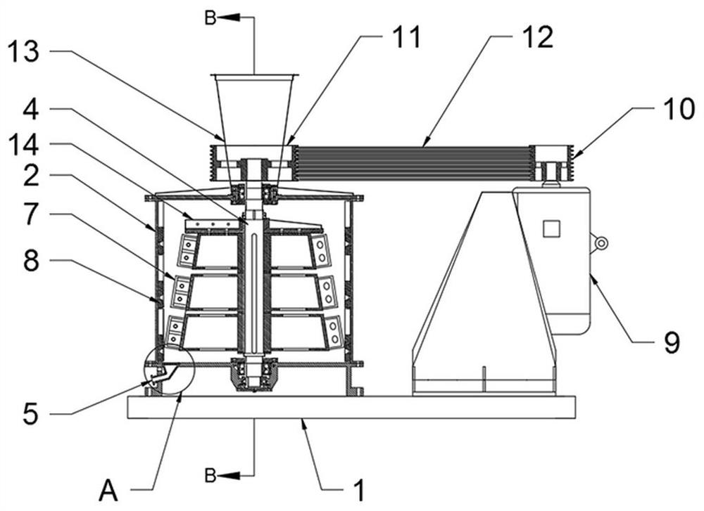
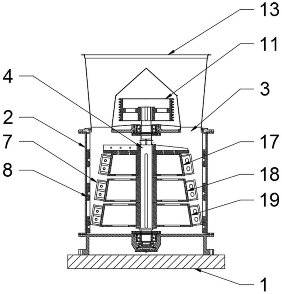
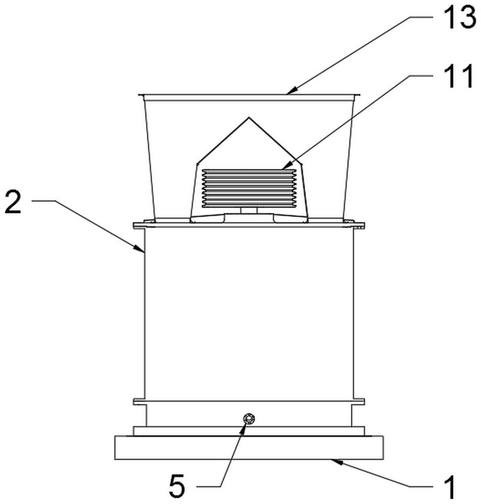
[0030] The metal scrap ball machine includes a base 1, a casing 2, and a driving device. The casing 2 is fixedly installed on the base 1. The casing 2 is cylindrical. The top of the casing 2 is provided with two feeding ports 3. The axis of the casing 2 is provided with a rotating shaft 4, and the two ends of the rotating shaft 4 are movably connected with the casing 2 through bearings. The driving device includes a driving motor 9, a driving wheel 10, a driven wheel 11, a transmission belt 12, a driving motor 9 and a base 1 Fixedly connected, the driving wheel 10 is fixedly installed on the rotating shaft of the driving motor 9, the driven wheel 11 is fixedly installed on the upper end of the rotating shaft 4, the driving wheel 10 and the driven wheel 11 are connected by power transmission belt 12, and the driving motor 9 uses a model of YX3-200L1 -2 high-power three-phase asynchronous AC motor, rated power 30kW, the bottom of the casing 2 is provided with a discharge port 5, ...

Embodiment 2

[0038] The metal scrap ball machine includes a base 1, a casing 2, and a driving device. The casing 2 is fixedly installed on the base 1. The casing 2 is cylindrical. The top of the casing 2 is provided with two feeding ports 3. The axis of the casing 2 is provided with a rotating shaft 4, and the two ends of the rotating shaft 4 are movably connected with the casing 2 through bearings. The driving device includes a driving motor 9, a driving wheel 10, a driven wheel 11, a transmission belt 12, a driving motor 9 and a base 1 Fixedly connected, the driving wheel 10 is fixedly installed on the rotating shaft of the driving motor 9, the driven wheel 11 is fixedly installed on the upper end of the rotating shaft 4, the driving wheel 10 and the driven wheel 11 are connected by power transmission belt 12, and the driving motor 9 uses a model of YX3-200L1 -2 high-power three-phase asynchronous AC motor, rated power 30kW, the bottom of the casing 2 is provided with a discharge port 5, ...


PUM


Abstract

The invention discloses a waste metal pelleting machine, and relates to the technical field of waste metal recovery equipment. The waste metal pelleting machine includes a base, a machine shell and adriving device; the top of the machine shell is provided with a feeding port, and a rotating shaft is arranged below the feeding port; the driving device is used for driving the rotating shaft to rotate; the bottom of the machine shell is provided with a discharging port; a plurality of cone pulleys are sequentially arranged on the rotating shaft from top to bottom, the cone pulleys are in a circular truncated cone shape, the diameters of the bottom surfaces of the cone pulleys are sequentially increased from top to bottom, and a plurality of flat hammers are fixedly mounted on the side surfaces of the cone pulleys; a plurality of lining plates are fixedly mounted on the inner wall of the machine shell; the rotating shaft, the flat hammers and the lining plates are all made of high-strength alloy steel; and a filtering device is a screen. The waste metal pelleting machine is used for crushing and extrusion formation of waste metals. Compared with an existing metal pelleting machine, the waste metal pelleting machine is capable of producing metal pellets smaller in size and more regular in shape and increasing the recovery price of the metal pellets and economic benefits.

Description

technical field [0001] The invention relates to the technical field of scrap metal recovery equipment, in particular to a metal scrap pelletizing machine. Background technique [0002] The number of domestic scrap metal scraps has been increasing sharply, and the demand for metals in my country is very large, so the utilization and recycling of scrap metals is very important. Contains a large amount of non-metallic impurities, such as plastic, paper, dust, and paint falling off the metal surface, etc. When metal smelting companies purchase scrap metal from waste recycling agencies, they have requirements for the content of non-metallic impurities in scrap metal and the size of scrap metal , The lower the impurity content, the smaller the size, the more regular the price, the higher the recycling price, thus creating the birth of metal recycling equipment, which is also the origin of the metal pellet machine. [0003] The metal ball machine uses the rotational force generated ...

Claims


Application Information

Patent Timeline
Patent Type & Authority Applications(China)
IPC IPC(8): B02C13/18B02C13/26B02C13/282B02C13/30
CPCB02C13/1814B02C13/26B02C13/282B02C13/30B02C2013/2825B02C2201/06
Inventor 刘吉
Owner 河南百瑞德环保科技有限公司
Why Eureka
Try Eureka