Brake pad perforating device

A drilling device and brake pad technology, applied in the field of brake pads, can solve the problems of drill bit shock absorption and buffering

Inactive Publication Date: 2020-12-25
衡阳迈特制动系统有限公司
8 Cites 3 Cited by

AI-Extracted Technical Summary

Problems solved by technology

[0005] The purpose of the present invention is to solve the shortcoming in the prior art that the impact...

Method used

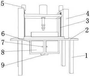
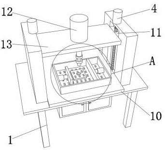
A kind of brake pad punching device, as shown in Figure 1-4, comprises support plate 2, and the bottom outer wall of described support plate 2 is fixed with four supporting feet 1 by bolt, and support plate 2 enlarges one side of top outer wall The shock-absorbing base 10 is fixed by bolts, the bottom of the support plate 2 is provided with a residue collection mechanism, the top of the support plate 2 is provided with a lifting mechanism, one side of the lifting mechanism is provided with a drilling assembly, and the top of the support plate 2 is provided with a fixing groove. The inner wall of the fixing groove is clamped with a filter plate 20, the top of the filter plate 20 is fixed with a fixed plate 2 19 by bolts, the outer wall of the top of the fixed plate 19 is fixed with an infrared receiver 16 by bolts, and the two sides of the fixed block 11 are provided with limiting components The impact force brought by the drilling is buffered by being provided with a shock-absorbing base 10, the height of the drilling is adjustable through the lifting mechanism, the brake pads are drilled through the drilling assembly, and the drilling is performed through the limit drilling. The brake pads are fixed at the limit to avoid deviation in drilling and increase the accuracy of drilling. The debris generated during drilling is collected through the debris collection mechanism to prevent debris from splashing and affecting the surrounding environment.
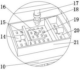
In order to limit and fix the brake pad when punching, as shown in Figures 2 and 3, the limit assembly includes two cylinders 14, two limit plates 15 and baffle plate 21, and baffle plate 21 passes through bolt Set on the top outer wall of the shock-absorbing base 10, one end of each cylinder 14 is set on one side inner wall of the baffle plate 21 by bolts, and one side outer wall of each limiting plate 15 is set on the other side of the cylinder 14 by bolts. One end: the baffle plate 21 is used to prevent the debris from splashing everywhere during drilling and affect the surrounding environment, and the two cylinders 14 are used to move laterally in the opposite direction, so that the brake pads can be clamped and fixed by the cylinder 14 driving the limit plate 15, Prevent deviation when drilling.
In order to make drilling more accurate, as shown in Figure 1-3, described drilling assembly comprises motor two 12, drill bit 17 and infrar...

Abstract

The invention discloses a brake pad perforating device which comprises a supporting plate. Four supporting legs are fixed to the outer wall of the bottom of the supporting plate through bolts, a damping base is fixed to one side of the outer wall of the enlarging top of the supporting plate through bolts, a residue collecting mechanism is arranged at the bottom of the supporting plate, a lifting mechanism is arranged at the top of the supporting plate, a drilling assembly is arranged on one side of the lifting mechanism, a fixing groove is formed in the top of the supporting plate, a filter plate is clamped to the inner wall of the fixing groove, a second fixing plate is fixed to the top of the filter plate through bolts, an infrared receiver is fixed to the outer wall of the top of the second fixing plate through bolts, and limiting assemblies are arranged on the two sides of the fixing block. According to the brake pad perforating device, infrared signals are transmitted through an infrared transmitter, the signals are received through the infrared receiver, so that an infrared ray is formed between the infrared transmitter and the infrared receiver, a drilling track drills alongthe infrared ray, so that drilling is more accurate; a second motor is started, and the second motor drives a drilling bit to rotate to conduct drilling work.

Application Domain

Drilling/boring measurement devicesMeasurement/indication equipments +5

Technology Topic

Electric machineryDrill hole +6

Image

  • Brake pad perforating device
  • Brake pad perforating device
  • Brake pad perforating device

Examples

  • Experimental program(1)

Example Embodiment

[0025]The technical solutions in the embodiments of the present invention will be clearly and completely described below in conjunction with the accompanying drawings in the embodiments of the present invention. Obviously, the described embodiments are only a part of the embodiments of the present invention, rather than all the embodiments.
[0026]In the description of the present invention, it should be understood that the terms "upper", "lower", "front", "rear", "left", "right", "top", "bottom", "inner", " The orientation or positional relationship indicated by “outside” is based on the orientation or positional relationship shown in the drawings, and is only for the convenience of describing the present invention and simplifying the description, and does not indicate or imply that the device or element referred to must have a specific orientation to The specific azimuth structure and operation cannot be understood as a limitation of the present invention.
[0027]A punching device for brake pads, such asFigure 1-4 As shown, the supporting plate 2 is included. The bottom outer wall of the supporting plate 2 is fixed with four supporting feet 1 by bolts. The side of the supporting plate 2 enlarged on the outer wall of the top is fixed with a shock-absorbing base 10 by bolts, and the bottom of the supporting plate 2 is provided with Residue collection mechanism, the top of the support plate 2 is provided with a lifting mechanism, one side of the lifting mechanism is provided with a drilling assembly, the top of the support plate 2 is provided with a fixing groove, the inner wall of the fixing groove is clamped with a filter plate 20, and the top of the filter plate 20 passes The fixing plate 2 19 is fixed by bolts. The top outer wall of the fixing plate 2 19 is fixed with an infrared receiver 16 by bolts. The two sides of the fixing block 11 are provided with limit components; the shock absorption base 10 is provided on the impact of drilling The force is buffered, the height of the drilling is adjustable through the lifting mechanism, the brake pad is drilled through the drilling assembly, and the brake pad is limited and fixed through the limit drilling to avoid the deviation of the drilling and increase the drilling The accuracy of the time, the debris generated during drilling is collected through the debris collection mechanism to prevent the debris from splashing and affecting the surrounding environment.
[0028]In order to collect the residue generated during drilling, such asfigure 1 As shown, the residue collection mechanism includes a box body 6, two handles 7, two box doors 8 and an exhaust fan 9. The top outer wall of the box body 6 is set on the bottom outer wall of the support plate 2 through bolts, and the box body 6 A mounting groove is provided on one side of the outer wall, and one side of the outer wall of each box door 8 is hinged to the inner wall of the mounting groove through a hinge, and each handle 7 is set on one side of the outer wall of the box door 8 through bolts. One side of the outer wall is set on the bottom outer wall of the box 6 by bolts; by starting the exhaust fan 9, the impeller in the exhaust fan 9 rotates at a high speed, thereby generating centrifugal force, so that the internal air of the exhaust fan 9 and the outside air form an air difference, making the outside air And the residue in the air is sucked into the box 6 due to the air difference, so as to achieve the effect of residue collection.
[0029]In order to adjust the height when drilling the brake pad, such asFigure 1-3As shown, the lifting mechanism includes two threaded rods 3, two fixing plates 4, two motors 5, a fixing block 11 and a connecting plate 13. The bottom outer wall of each fixing plate 4 is set on the support by bolts. On the outer wall of the top of the board 2, one side outer wall of each fixed board 4 is provided with a sliding groove, and each threaded rod 3 is arranged on the output end of each motor 5 through a uniform coupling, and each fixed block 11 They are all arranged on the outer circumferential wall of the threaded rod 3 through threads, one side of the outer wall of each motor 5 is arranged on the top outer wall of the fixing plate 4 by bolts, and the outer walls on both sides of the connecting plate 13 are arranged on the fixing block 11 by bolts. On the opposite side of the outer wall; by starting the motor 5, the output end of the motor 5 drives the threaded rod 3 to rotate in the chute, the fixed block 11 is rotated by the thread on the threaded rod 3, so that the fixed block 11 is on the threaded rod The height of 3 can be adjusted, so that the height of the connecting plate 13 can be adjusted to achieve the effect of lifting adjustment.
[0030]In order to make drilling more precise, such asFigure 1-3As shown, the drilling assembly includes a second motor 12, a drill bit 17, and an infrared transmitter 18. One side of the outer wall of the second motor 12 is set on the top outer wall of the connecting plate 13 through bolts, and one end of the drill bit 17 is set on the top outer wall of the connecting plate 13 through a coupling. On the output end of the second motor 12, the infrared transmitter 18 is arranged on one side of the outer wall of the drill bit 17 through a bolt; the infrared signal is transmitted by the infrared transmitter 18, and the infrared receiver 16 receives the signal, so that the infrared transmitter 18 and the infrared receiver 16 An infrared ray is formed between the drilling track to drill along the infrared ray, so that the drilling is more precise. Start the motor two 12, so that the output end of the motor two 12 drives the drill bit 17 to rotate, and the drill is drilled by the lifting adjustment of the connecting plate 13. Hole work.
[0031]In order to limit and fix the brake pads when drilling holes, such asfigure 2 with3As shown, the limit assembly includes two cylinders 14, two limit plates 15 and a baffle 21. The baffle 21 is provided on the top outer wall of the shock-absorbing base 10 by bolts, and one end of each cylinder 14 is passed through bolts. It is arranged on the inner wall of one side of the baffle 21, and the outer wall of each limiting plate 15 is installed on the other end of the cylinder 14 by bolts; the baffle 21 prevents debris from splashing during drilling and affecting the surrounding environment. The two cylinders 14 are used for lateral movement in opposite directions, so that the cylinder 14 can drive the limit plate 15 to clamp and fix the brake pads to prevent deviation during drilling.
[0032]In order to buffer the impact force generated during drilling, such asfigure 2 ,3As shown in and 4, the shock-absorbing base 10 is composed of more than three conductive columns 22, a shock-absorbing plate 23, and a bearing plate 24. The top outer wall of the shock-absorbing plate 23 is installed on the top inner wall of the shock-absorbing base 10 by bolts. The plate 24 is arranged on the inner wall of the bottom of the shock-absorbing base 10 by bolts, and both ends of each conductive column 22 are arranged on the outer wall of the shock-absorbing plate 23 and the opposite side of the bearing plate 24 by bolts; The impact force caused by the hole is buffered and damped, and the force received by the shock-absorbing plate 23 is transmitted and dispersed through the conductive column 22 to reduce the pressure on the shock-absorbing plate 23, and the drilling equipment is lifted and supported by the load-bearing plate 24 effect.
[0033]Working principle: When this embodiment is in use, the motor 5 is started, so that the output end of the motor 5 drives the threaded rod 3 to rotate in the chute, and the fixed block 11 is rotated by the thread on the threaded rod 3, so that the fixed block 11 is The height of the threaded rod 3 is adjustable, so that the height of the connecting plate 13 is adjustable. The infrared transmitter 18 emits infrared signals, and the infrared receiver 16 receives the signals, so that a line of infrared rays is formed between the infrared transmitter 18 and the infrared receiver 16. The drilling track is drilled along the infrared rays, so that the drilling is more accurate. Start the motor two 12, so that the output end of the motor two 12 drives the drill bit 17 to rotate, and the drilling is performed by the lifting adjustment of the connecting plate 13, and the baffle 21 To prevent the debris from splashing around during drilling and affecting the surrounding environment, the two cylinders 14 are used to move in opposite directions, so that the cylinder 14 can drive the limit plate 15 to clamp and fix the brake pads to prevent occurrence during drilling. Deviation, the exhaust fan 9 is started, the impeller in the exhaust fan 9 rotates at a high speed, thereby generating centrifugal force, so that the internal air of the exhaust fan 9 and the outside air form an air difference, so that the external air and the residue in the air are sucked into the box 6 due to the air difference Inside, the residue is collected.
[0034]The above are only preferred specific embodiments of the present invention, but the protection scope of the present invention is not limited to this. Anyone familiar with the technical field within the technical scope disclosed by the present invention, according to the technical solution Equivalent replacements or changes to its inventive concept should all fall within the protection scope of the present invention.

PUM

no PUM

Description & Claims & Application Information

We can also present the details of the Description, Claims and Application information to help users get a comprehensive understanding of the technical details of the patent, such as background art, summary of invention, brief description of drawings, description of embodiments, and other original content. On the other hand, users can also determine the specific scope of protection of the technology through the list of claims; as well as understand the changes in the life cycle of the technology with the presentation of the patent timeline. Login to view more.
Why Eureka
Try Eureka