Noise reduction equipment applied to pneumatic grinding machine

A pneumatic grinder and noise reduction technology, applied in the field of noise reduction, can solve problems such as secondary noise, different flow directions, pipe wall collision, etc., and achieve the effect of slow gas flow

Inactive Publication Date: 2020-12-25
广州凯宇信息技术有限公司
View PDF0 Cites 0 Cited by
  • Summary
  • Abstract
  • Description
  • Claims
  • Application Information

AI Technical Summary

Problems solved by technology

[0004] Since the drive of the air motor requires continuous input of external gas, the flow direction of the external gas is scattered. When it enters the tube cavity from the air inlet for transmission, it is easy to collide with the tube wall due to the different flow directions. The reaction force after the collision has a negative impact on the noise reduction equipment. The strong punching force causes the noise reduction equipment to vibrate in the lumen, causing secondary noise

Method used


Image

  • Noise reduction equipment applied to pneumatic grinding machine
  • Noise reduction equipment applied to pneumatic grinding machine
  • Noise reduction equipment applied to pneumatic grinding machine

Examples


Embodiment 1

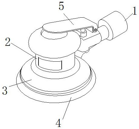
[0028] as attached figure 1 To attach Image 6 Shown:

[0029] The invention provides a noise reduction device applied to a pneumatic grinder, the structure of which includes an air inlet 1, a motor shield 2, a grinding shell 3, a grinding head 4, and a switch handle 5, and one end of the air inlet 1 is connected to the The outside of the motor casing 2 is connected, the grinding casing 3 is embedded and installed at the bottom of the motor casing 2, the grinding head 4 is movably connected to the bottom of the grinding casing 3, and one end of the switch pressure handle 5 is connected to the air intake The top of port 1 is connected, and the switch pressure handle 5 moves above the motor shield 2.

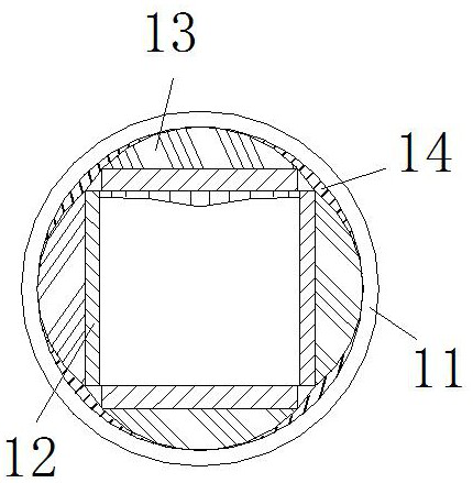
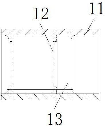
[0030] The air inlet 1 is provided with a pipe 11, a noise reducer 12, a petal block 13, and a corner block 14, the noise reducer 12 is located in the middle of the inner side of the pipe 11, and the outer wall of the petal block 13 is connected to the On the inner side wall of...

Embodiment 2

[0036] as attached Figure 7 to attach Figure 8 Shown:

[0037] Wherein, the corner block 14 is provided with a retaining flap b1, an angle stabilizing end b2, and a stabilizing layer b3, the retaining flap b1 is embedded and connected on the inner upper wall of the corner resisting block 14, and the corner stabilizing end b2 is fixed Installed under the retaining flap b1, the stabilizing layer b3 is connected to both sides of the angle-stabilizing end b2, the retaining flap b1 is in the shape of an ellipse to ensure uniform stress, and the overall shape of the angle-stabilizing end b2 is fixed at It can return to its original shape after stretching.

[0038] Wherein, the stabilizing layer b3 is provided with a pointed insertion section b31, an inner pressure layer b32, a supporting arc block b33, an inner buttress b34, and a pocket b35, and the pointed insertion section b31 is located at the center of the stabilizing layer b3. At the most side angle position, the stretchi...


PUM


Abstract

The invention discloses a noise reduction equipment applied to a pneumatic grinding machine. The noise reduction equipment structurally comprises an air inlet, a motor protection shell, a grinding shell, a grinding head and a switch pressing handle. Due to the fact that extrusion force is applied to a lower abutting edge by gas impact force, the lower abutting edge is bent in the arc direction, anauxiliary block makes inclined compression movement, a connecting and pulling section is pulled, and thus the front side of a first through opening is expanded; part of gas is guided into the inner side of a hook guide head through the first through opening and moves together with gas guided by the lower abutting edge, and part of gas flows out from a second through opening, so that the gas is prevented from being gathered on the inner side of the lower abutting edge; the gas flows slowly, and an inner pressing layer is jacked and pressed, so that a supporting and pressing arc block is pressed to bend in the arc direction; meanwhile, the supporting and pressing arc block jacks an inner abutting edge strip, and the inner abutting edge strip extrudes a pocket supporting bag body, so that the pocket supporting bag body tends to be transversely flattened and is more attached to the inner side of a pipeline; and thus, a corner abutting block bears the jacking pressure of a noise reducer and isolate contact with the inner side of the pipeline, and secondary noise generated by sharp touch is avoided.

Description

technical field [0001] The invention belongs to the field of noise reduction, and more specifically relates to a noise reduction device applied to a pneumatic grinder. Background technique [0002] Pneumatic grinding machine uses gas to drive the air motor, so that it drives the grinding head to rotate on the metal layer, paint layer, putty layer and other layers for grinding. The noise reducer installed on the pneumatic grinding machine can reduce the transmission along the pipeline when the gas is fed in. The noise can not only allow the gas to circulate but also effectively reduce the noise generated by the aerodynamic force. [0003] Based on the inventor's discovery above, the noise reduction equipment of existing pneumatic grinders has the following deficiencies: [0004] Since the drive of the air motor requires continuous input of external gas, the flow direction of the external gas is scattered. When it enters the tube cavity from the air inlet for transmission, it...

Claims


Application Information

Patent Timeline
Patent Type & Authority Applications(China)
IPC IPC(8): B24B23/02B24B41/02B24B41/04
CPCB24B23/026B24B41/02B24B41/04
Inventor 王志萍
Owner 广州凯宇信息技术有限公司
Why Eureka
Try Eureka