Mechanical arm for mine

A technology of a mechanical arm and a mechanical swing arm, applied in the field of mechanical arms, can solve the problems of violent shaking of the mechanical arm, potential safety hazards, laborious drilling, etc., to achieve stability without drilling, stable swing process, and increase the force on the bottom area effect

Inactive Publication Date: 2020-12-25
李红兵
View PDF0 Cites 0 Cited by
  • Summary
  • Abstract
  • Description
  • Claims
  • Application Information

AI Technical Summary

Problems solved by technology

[0003] The existing technology has the following disadvantages: in the process of working in the mine environment, it is necessary to use the mechanical arm to lift and transfer various small equipment, and in the process of installing the mechanical arm, the traditional method is to use screws. It is quite inconvenient, and it is more laborious to drill additional holes on some auxiliary loading platform vehicles. When individual screws are not locked, the mechanical arm will easily shake violently when it swings, which indirectly brings some safety hazards

Method used


Image

  • Mechanical arm for mine
  • Mechanical arm for mine
  • Mechanical arm for mine

Examples


no. 1 example

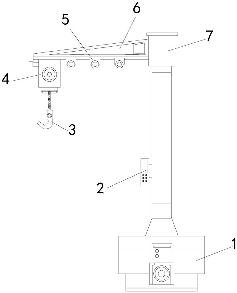
[0026] see Figure 1-Figure 3 , the present invention provides a mechanical arm technical solution for mines: its structure includes: a fixed frame body 1, a controller 2, a hoisting head 3, a power crane 4, a transmission shaft wheel 5, a mechanical swing arm 6, and a supporting main rod 7 , the hoisting head 3 is installed under the power crane 4 and fastened with the power crane 4, the power crane 4 is arranged under the mechanical swing arm 6, and the mechanical swing arm 6 is locked with the power crane 4, The power hoist 4 is electrically connected to the controller 2 through the transmission shaft wheel 5, the controller 2 is arranged at the lower end of the supporting main rod 7, and a fixed frame body 1 is arranged below the supporting main rod 7, and the fixed frame body 1 is locked with the supporting main rod 7, and the fixed frame body 1 includes a support plate device a, a stability maintenance device b, a buffer pad c, an assembly steel frame d, and a connection...

no. 2 example

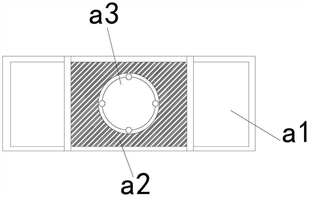
[0030] see Figure 4-Figure 6 , the present invention provides a mechanical arm technical solution for mines: its structure includes: the adjustment plate device a1 includes an adjustment shaft tube a11, a side slide plate a12, a locking plate a13, and a connecting sleeve layer a14, and the inside of the side slide plate a12 is provided with There is a locking plate a13 and it is welded with the locking plate a13. The inner side of the locking plate a13 is provided with an adjustment shaft tube a11. The inner side of the adjustment shaft tube a11 is provided with a connection sleeve layer a14. The gap between the connection sleeve layer a14 and the adjustment shaft tube a11 Cooperate.

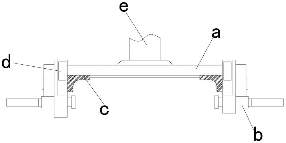
[0031] The stability maintenance device includes a snap-fit ​​frame device b1, an electric storage tube b2, a telescopic shaft b3, and a travel motor b4. The snap-fit ​​frame device b1 is installed on the front end of the telescopic shaft b3, and the telescopic shaft b3 runs through the travel ...


PUM


Abstract

The invention discloses a mechanical arm for a mine. The mechanical arm structurally comprises a fixed frame body, a controller, a hoisting head, a power crane, a transmission shaft wheel, a mechanical swing arm and a supporting main rod; when equipment is used, by means of an arranged fixed frame mechanism, the situation that in the mine environment working process, screw fixation is adopted in atraditional mode, the mode is quite inconvenient, additional punching needs to be conducted on some auxiliary loading platform vehicles, labor is wasted, when individual screws are not locked and themechanical arm swings, violent shaking is likely to happen, and some potential safety hazards are indirectly caused, so that through cooperation of a supporting plate device, the stress area of the bottom of the equipment is increased, and the swing process of the mechanical arm is more stable; meanwhile, through mutual cooperation of a stability maintaining device and a buffer cushion, a clamping type structure is adopted, nesting and clamping can be conducted on the mechanical arm and multiple platforms, and therefore the fixing mode is more flexible, punching is avoided, and the stabilityis higher.

Description

technical field [0001] The invention relates to a mechanical arm used in mines, which belongs to the field of mining equipment. Background technique [0002] The mining industry is one of the important basic industries that provide equipment for the mining and processing of solid raw materials, materials and fuels. It serves important basic industrial sectors such as ferrous and nonferrous metallurgy, coal building materials, chemical industry, and nuclear industry. Its products are widely used in transportation, railways, and water conservancy. There are also a large number of applications in the construction of basic departments such as hydropower, and this process needs to be applied to various types of robotic arm equipment for cooperation. [0003] The existing technology has the following disadvantages: in the process of working in the mine environment, it is necessary to use the mechanical arm to lift and transfer various small equipment, and in the process of install...

Claims


Application Information

Patent Timeline
Patent Type & Authority Applications(China)
IPC IPC(8): B66C23/02B66C23/62B66C23/64B66C23/88B66C13/18
CPCB66C13/18B66C23/02B66C23/62B66C23/64B66C23/88B66C2700/03
Inventor 李红兵
Owner 李红兵
Why Eureka
Try Eureka